Skeletal animation relies on inheritance: A weight on a bone at the end of a bone chain affects all movements induced by any of the bones in the chain. I can explain this best with an example:
Theory corner: Weight inheritance and Collision Volumes
Weighting the hands
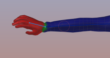
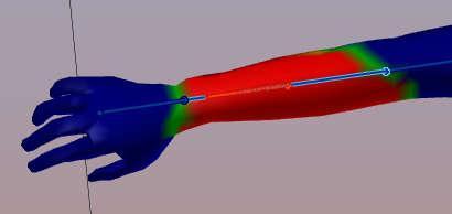
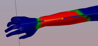
Think about the Hand part of your character. The Secondlife System, character has its hands weighted only to the Wrist bones. Only near the joint to the lower elbow bones we see that a few vertices have 2 weights distributed between the wrist and the lower elbow bone (the green zone in the image)
Bone inheritance
Now you can rotate the wrist bone relative to the lower arms. Then the mesh moves along with the bone (on the red areas) and behaves well near the joint (on the green areas, stretches without getting too distorted)
But when you move the lower arms instead of the wrist bones, then the hands still move along with the arms, although most vertices are only weighted to the wrist bones! This is because the Wrist bones are children of the Elbow Bones. When the elbow bones move, then also the wrist bones move (because of the bone hierarchy). And because the fingers are weighted to the wrist bone, they move correctly along with the arm.
Typical Weight count
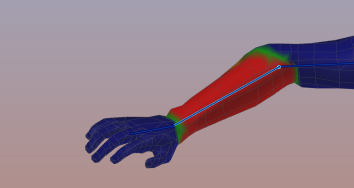
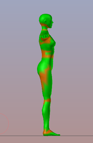
When you put all of this together then you realize that most of your vertices have only one weight (indicated as red area), while near the joints the vertices typically have no more than 2 weights. In fact we have seen above that the original SL Avatar has no vertex weighted to more than 2 bones.
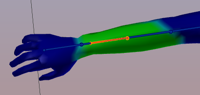
Green areas have 2 weights on each vertex
And when you look in more detail then you see that the areas where a vertex has 2 weights are always close to the joints. Does this make sense now?
This page is about the principles of fitted Mesh. We strongly recommend that you first read this page before you attempt to go ahead and do practical work. However here are the links to the other pages on this topic:
The Nuts & Bolts
When we step into fitted mesh the situation gets a bit more complicated. Technically Fitted mesh is nothing special. It just makes use of a subset of the Skeleton, namely the set of Collision Volume Bones, where each Collision Volume Bone is clamped to a corresponding classic bone. Thus building tightly coupled Bone Pairs.
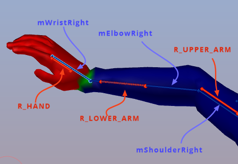
In the image aside you see for example the 3 bone pairs:
- R_HAND is clamped to mWristRight
- R_LOWER_ARM is clamped to mElbowRight
- R_UPPER_ARM is clamped to mShoulderRight
Fitting Bones
Due to the clamping the collision Volume always moves and rotates along with the bone to which it is clamped. With other words each bone pair [Collision Volume + Classic Bone] can be seen as one unbreakable unit. Lets name such a bone pair a FittingBone consisting of an mBone (a classical bone) and a cBone (a collision Volume).
When we look at classic Weighting then we only deal with the classic mBones. The cBones are completely ignored by the animation system and things are rather easy and well organized (left side of image).
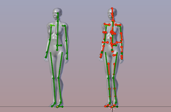
Left: regular Bones; Right: regular + cBones
For Fitted Mesh many users think they just need to replace the classic mBone weighting by the new cBone weighting, thus only use the cBones for fitted mesh. But this is not true. In general we have to deal with all cBones and all mBones at the same time when we make fitted mesh (right side of image)!
Animating Fitted mesh
Regarding the animation of your characters, it does not matter which bone of a FittingBone pair gets which weight:
- You could place all weight to the mBone
to get a pure classic weighting. - or you could place all weight on the cBone
to get “Fully Fitted Mesh” weighting, - or you can distribute the weight between
the 2 bones in any way you like.
In any case it is the weight sum of the Collision Volume and the corresponding classic Bone within a FittingBone pair that affects the animation, nothing else!
All weights on the mBone (Classic)
Weights distributed between mBone and cBone
All weights on the cBone (fully Fitted)
The animation pitfall
Lets say your mesh is perfectly weighted to the classic bones. Now you want to convert this to fitted mesh. So you just add weight to the Collision Volume Bones and all is done…
But wait, when you add weight to a collision Volume, then the weight sum on your vertices raises above 1.0 (because you added weight) ops… well, Blender is a bit clever here (and also a bit confusing for the user), it allows you to create weight sums > 1. But then it internally corrects the numbers by normalizing them before using them. Normalizing enforces that the weight sum is 1.0 again.
So what? All is well again, no?…
well, you have added weight to the collision volume bone, right? But the weight sum must be kept at 1.
Hence this added weight must have been taken away from somewhere… So by adding weight to the cBone we reduce the weight on all other bones.
This is not an issue where you only have one single weight (the red zones in the images above). But wherever you already had 2 or more weights on classic bones, adding weight to a corresponding Collision volume most probably destroys your weights on the classic bones. And unfortunately this always happens near the joints.
Shaping Fitted Mesh
The Collision Volume Bones are used to add volume to your mesh. That is, the cBones provide a scale vector to make your mesh bigger or smaller depending on the amount of weight on the CollisionVolume Bone.
However you never “see” this vector anywhere. But you modify its value by using the Appearance Sliders. And as a result your mesh blows up or shrinks whenever a vertex is weighted to a collision volume bone AND the sliders are not in the neutral state.
Caveat: But all of this does not happen when your armature is in its default Shape (neutral shape) simply because there the scale vector is neutral.
Practical tip
When you want to do Fitted Mesh, then please select your Mesh, then step into the Avastar Skinning panel and ensure that your Mesh is set to ‘SL Appearance’
And then move the appearance sliders of interest out of the neutral setting. otherwise you can not see any change in your fitted mesh!
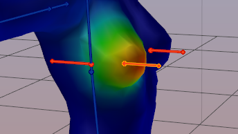
Weights on RIGHT_PEC, Breast Size appearance slider set to 0
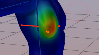
Weights on RIGHT_PEC, Breast Size appearance slider set to 50 (neutral)
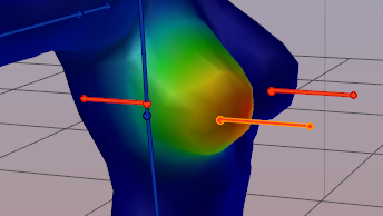
Weights on RIGHT_PEC,
Breast Size appearance slider set to 100
Weight Count for Fitted Mesh
We learned above that the FittingBones consist of bone pairs. So when we look at the joint of any 2 FittingBones we actually look at 4 bones (and not at 2 bones as in the classic weighting) Thus at the end you see that for Fitted mesh you typically need the double amount of weights on each vertex (weight the collision volumes for shaping, weight the classic bones for animating)
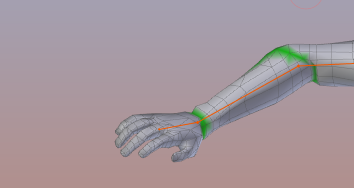
As a consequence a fitted mesh character does in general use 4 weights near the joints and 2 weights anywhere else.
Green: 2 weights, Orange: 4 weights
Tweaking Weights of a subset of vertices
In the previous document we have managed to get the Mesh mostly fixed on its upper part. However we do have some parts where the System character mesh pokes through our skirt.
We can use the vertex group editor to tweak the values of mPelvis and mHipRight for each of the badly placed vertices on the butt. It is a lot of small editing and we do this only for educational purpose. Normally you would not edit weights in that way because it is by far too time consuming.

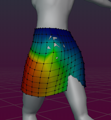
However, after a couple of minutes and after tweaking a few vertices we might end up with something like in the image to the right. This is better, but still not good. Why that ?
Topology rules them all…
The Skirt butt gives us so much headache because the Avatar’s butt and the skirt’s butt use a slightly different mesh topology. And … when you take a look at how the avatar’s But animates, then you see, surprise, surprise…
It is actually not animated… what ? well, go and see by yourself. Our walk cycle does not affect the Avatar Butt at all, oops…
Well, on a second thought this is not entirely wrong for the avatar. But for a skirt we might want to get a somewhat more subtle weighting. So we have a problem… (but the solution comes next)
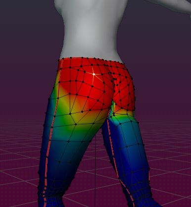
The red area is only tied to the mPelvis bone
The 5 seconds fix …
The fix is banal: In mesh Edit Mode: Lift the faces up a bit along their normals…:

Well, just a tiny lifting of the important parts is necessary and then all goes well. Note: I also have smoothed the weights a bit as you an see on the yellow/green parts.
So now lets turn to the real issue, that is the poke through on the upper legs…
An important observation
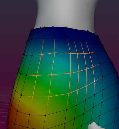
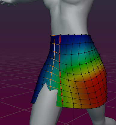
For better orientation I have placed a seam marker on the symmetry line of the skirt (the dark red edge loop, see image). And I moved the timeline to 30, that is where the poke through is maximal for the right leg. And furthermore I have selected the edge loop that needs the most fixing.
We now must lift the bottom of the selected edge loop above the leg’s surface. We will do that with the Levels tool.
The Levels tool has 2 purposes:
- It can add a constant offset to the weights of the current vertex selection.
- and it can scale up the weights of the current vertex selection.
We will use the scale function to lift the selected edge loop up until the poke through disappears.
- Select the edge loop.
- Ensure you have selected the mHipRightt weight group (in the Vertex group List).
- Below the Top Bar of the 3D Viewport open the Mesh Menu and locate the Levels tool (see image)
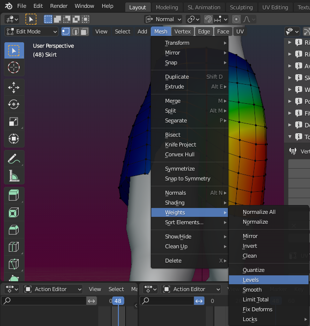
- Now call the Levels Tool.
- In the Operator panel lower the gain until the surface of the skirt gets completely pulled out (that happens around Gain = 0.08).
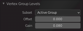
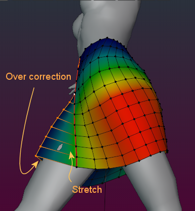
We end up with something like in the image aside. Please take care that you do not over correct the weights as shown in the image. You can get this fixed by adding a bit to the gain.
In the next chapter we will take care of the stretched mesh.