Abstract
In this document we describe a practical approach to prepare a model for usage in Secondlife and how to create a Developer kit for this model. We will begin with a Mesh model which is initially in a somewhat unfortunate state, a situation that might happen while actively working on a real project and forgot things to do or undo, while focusing on the main part, the model itself.
The approach described here just happens to need many different steps for cleaning up and preparation. So we can demonstrate how to do each of those steps. Of course your situation may be completely different and our approach is just one way to go. But studying this document may help you to get your project into a more suitable shape as well. Furthermore you will end up with a clean Developer kit that will surely make your own customers very happy.
The Scenario
Lets assume you have been working on your model for some time and you have tried out many things until now. Finally you are satisfied with your model. Then you have tried to rig your model and prepare it to work with Avastar. But you encountered a few issues and finally ended up in a messy situation.
So… we have a practical every day example. we have run into problems and we need to get out of the bad place we are in right now. And make this awesome…
I will show you now how you can rescue your model and get it to work. Actually we want to start with a clean not rigged model. So in the very first step we will cleanup the entire scene (equivalent to cleanup our desk)…
Clean the project file
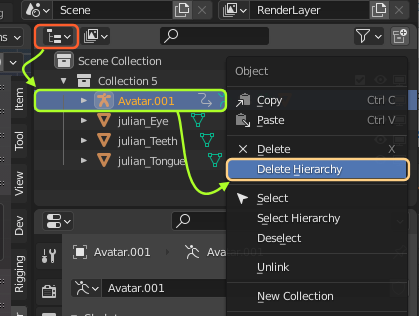
Remove unneeded Objects
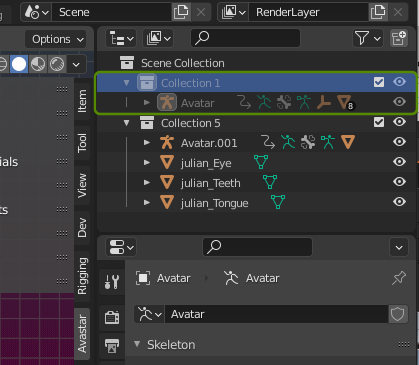
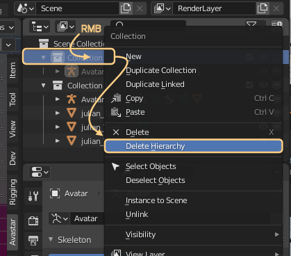
- Open the Outliner
- Select unneeded Elements (all together or one by one)
- RMB – Delete Hierarchy
- Do this for all elements which are unrelated to your model
Be rigorous, delete everything you do not really need. Your customers will be thankful.
Note: If you unintentionally deleted something then very often you can get back to the previous step by typing CTRL-Z (or Edit -> Undo on the Top Menu bar)
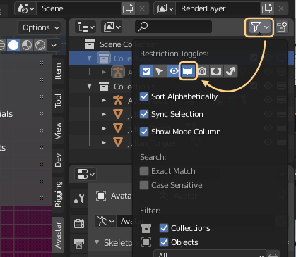
Tip: If a collection is greyed out then it is disabled. If you want to inspect it before deleting, then enable the appropriate filter in the Outliner’s top menu bar. then you can inspect the item and decide if it needs to be removed.
Take care: If your mesh model is parented to an Armature, do not delete the armature yet. See further down.
You can remove entire hierarchies, here the entire collection gets removed, even if it is disabled.
Remove not needed UV Maps from your Meshes
- Open the Properties window
- Lookup the UV Map panel
- Remove all UV Maps that you no longer need
Note: In this particular model the vertex group rebake tool created bad results. The rebaked UV map is useless, so we can remove it. If your models uses multiple UV Maps on purpose, then there is no need to remove or replace them. Just ignore this step in that case.

Remove vertex groups (if necessary)
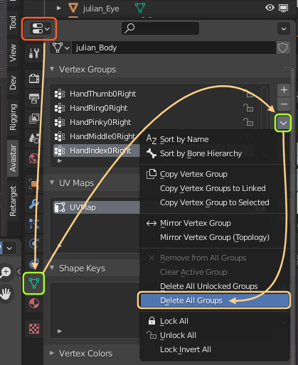
- Select your Mesh in Object mode
- Open the Properties window
- Lookup the Vertex groups panel
- From the function drop down select Delete all Groups
Note: In this particular case the vertex groups are broken. If your model has properly working vertex groups then keep them. Just ignore this step in that case.
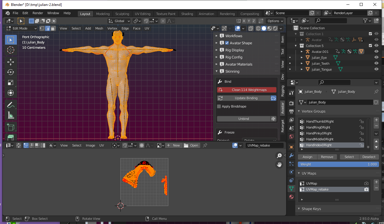
Unbind the model from an Avastar rig
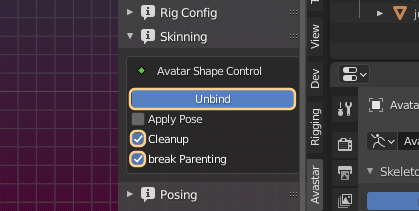
If your model is bound to an Avastar Rig
- Select the Rig in Object mode
- Open the N-Panel
- Locate the Avastar – Skinning panel
- Enable the X icon (cleanup Avastar properties)
- Unbind
Unbind the model from a Blender rig
If your model is rigged to another armature (not an Avastar) then:
- Select the Mesh model in Object mode
- Press ALT P
- In the popup Menu click Clear and Keep Transformation
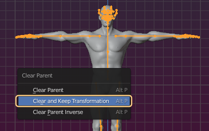
- Now you can safely remove the armature hierarchy (as explained further up)
- You now may want to save the cleaned scene into a new blend file.
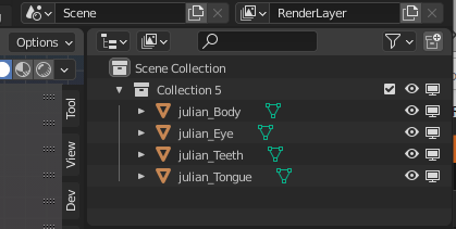
We end up with a Blend file that contains only the meshes of our model.
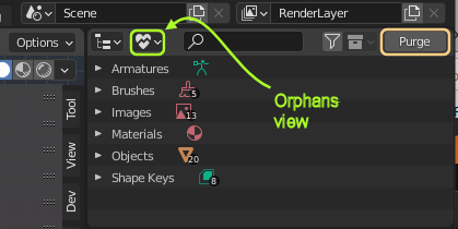
We can take it even one step further and purge all unnecessary data that might have been added to the scene and still lingers around in the blender file.
You need to select the Orphan view in the Outliner, then you can purge all not needed data. You might need to purge multiple times, because purged objects possibly leave other items behind as orphans.
First milestone: Clean desk achieved
By now we have cleaned up the scene. We removed the armatures and we have cleaned up all meshes, so that we now can restart our binding. But before we do that we do some more cleaning up, this time on the mesh itself.
Remind: We want to create a perfect (ok, almost perfect) mesh model that can be used as Avatar for SL and also as a Developerkit for usage within Blender and other 3D content creation tools.
Inspect and fix the model
To check:
- Topology
- Symmetry of Mesh
- UV Mapping
Please make sure you have a clean situation as describe in the First Milestone above:
- Take care that only the Mesh is selected in Object mode.
- Make sure the mesh is not yet bound to any armature
- Remove any unnecessary elements from the Blend file.
- Always keep a clean desk!
Topology
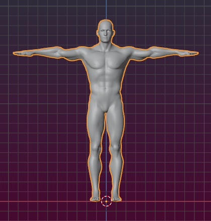
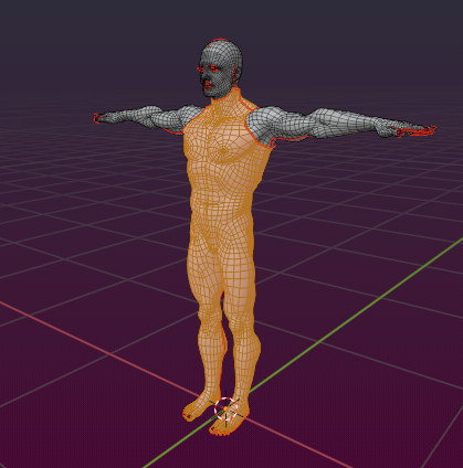
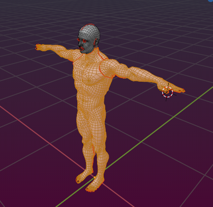
We aim for a smooth shape with as few polygons as possible. Lets compare the Mesh with the SL Avatar
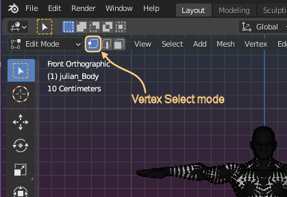
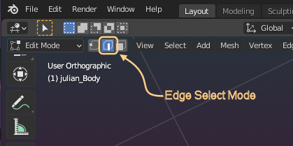
- Go to Edit mode
In the image i have enable Edge select mode. This shows the mesh topology a bit nicer than the vertex select mode.
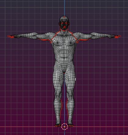
The mesh (in edit mode)
- Open the Avastar – Mesh Info Panel
- Click the Refresh statistic Button to get the Mesh info
- Check the vertex count and the Face Count
Compare to the SL System character:
Vertices
Triangles
Faces
3618 Verts
7186 Tris
7186 Polys
10774 Verts
21204 Tris
10624 Polys
The numbers sound OK. The Mesh could be optimized still, but overall the model seems to be well suited for SL. We will not

Symmetry
This video is for an older version of Avastar. But its content is still valid.
Although there is no strict rule about symmetry, it makes a lot of sense to make sure that your model is symmetric. This will later save you and your customers a lot of work.
Note: If you are familiar with Blender then you certainly know about the mirror modifier. While you can use this modifier to make symmetric models, sometimes you have a situation where a model is overall symmetric, but has small deviations. And maybe you only want to work on a part of a mesh to make it symmetric.
We have added a symmetry tool to Avastar that is based on the Blender symmetry tool but it may be a little bit easier to use. This tool can show you where asymmetries are and it can fix them. Here we go:
- Make sure the mesh is in vertex select mode
- Make a visual check if the Mesh is symmetric to the Origin.
ok, in our case a Quick inspection shows that the mesh looks symmetric but it is slightly shifted. We need to fix that by shifting the entire mesh (select all vertices) to the right in Edit mode.
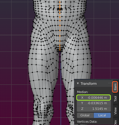
Close inspection: Mesh is shifted sideways by ~0.6 cm
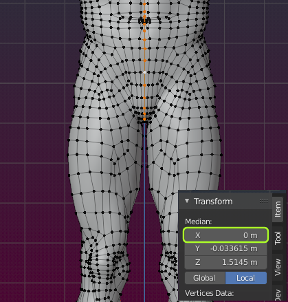
Manual shifting all (not just the center) vertices to the left by ~0.6446 cm
By visual inspection the mesh is now symmetric. But lets check this with Avastar
- Make Sure the mesh is in edit mode
- Open the N-Panel
- Open the Avastar Tool Box
- Find the Vertex Tools
- Click the Asymmetries Operator
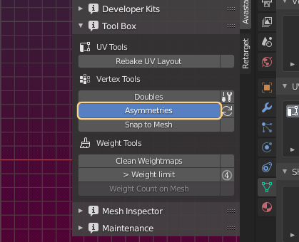
The operator selects all vertices which have no symmetry partner on the other side of the X axis.
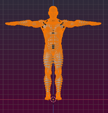
We see that almost all vertices are selected. This is because our visual fix was not precise enough.
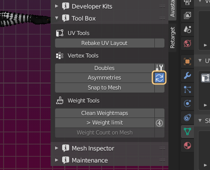
However we can force symmetry. Make sure the vertices are still selected (see previous step). Now click the Fix Asymmetries Operator (the double arrow in the image). this will fix most of the asymmetries.
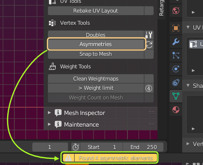
We can check if everything is now symmetric by calling the Asymmetries Opreator again, and see…
This time only 4 vertices are reported as being asymmetric. So, you need to manually make them symmetric. This may be a challenge, especially because you first need to find the vertices on the mesh. They are selected, but in this special case its very hard to actually find where they are.
Tip: Use CTRL-I to invert the selection, then hide selected. Now only the asymmetric vertices are visible and you can locate them easily..
Once you have symmetrized all vertices, lets proceed by checking if the edges are symmetric as well.
- Make sure the mesh is in edge select mode
- Open the Avastar Tool Box
- Click the Find Asymmetries Operator
Now all edges are selected which are not symmetric. In our mesh we can find a few of such edges despite the fact that all vertices are symmetric. The reason in our case is that some edges connect to the wrong vertices. So, automatic fixing does not work nicely here. We need to fix the edges manually. Then, when we are done with fixing the edges, then finally we need to do this very same procedure one last time to check the symmetry of the faces.
Hint: In general when vertices and edges are symmetric then any asymmetry in faces can only come from missing faces.
When the mesh is reported to be symmetric regarding vertices, edges AND faces, then we are done and the mesh is ready for the next step. Save it now!
Second Milestone achieved: A Clean mesh
We have adjust the entire mesh to a model symmetric on the X-Axis. We now need to turn our focus to UV Mapping (texturing)
UV Mapping

I assume you know enough about UV mapping so that we can dive into this without further explanations.If you need a refresh, then the first 6 minutes of this video may give you some hints (the video uses an older version of Blender though)
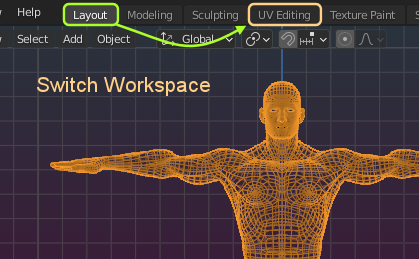
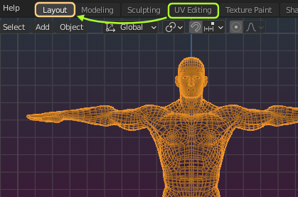
Our aim is to create a useful and easy to maintain UV Map. Our mesh happens to already being UV unwrapped. Lets inspect the map. For this purpose we first switch our workspace to UV Editing.
- Then enter Edit mode
- and choose Face select mode (this is important!)
we start with inspecting the body:
- Hover the mouse over the upper body in the 3D viewport
- Then press l (lower case ‘L’)
- You now have selected a UV island (see below)
Now the upper body except the arms (and the toes) is selected.
Hint: Using ‘L’ to select an entire body part works only in face select mode. Note that the borders of a body part are defined by seams.
On the left side (in the UV Editor) you can see the current UV Map of the upper body. This is a UV island – an isolated part of the U map that is not connected to any other UV faces on the map.
This partial map (the island) does not look wrong, it covers most part of the map space, it looks symmetric. So we can keep it as it is.
Lets proceed with the arms…
- Hover the mouse over the left arm, then press ‘l’ (lower case ‘L’)
- Do the same for the right arm
Now we can see in the UV Map where the arms have been placed (next image)…
The arms have been placed on the UV Map besides the body. Again there is not much wrong here. So lets keep this as it is and proceed …
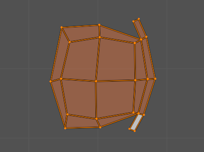
Now we look at the toes and nails. this is where things start to become interesting…
Lets switch to wireframe mode, then we can select additional vertices easier
- Make sure the mouse hovers over the 3D Viewport.
- Now press ‘z’ – a pie menu opens.
- From the menu select Wireframe.
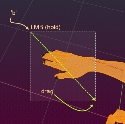
- press ‘b’ for border select.
- now click (LMB) somewhere near one hand.
- while keeping the button down move the mouse until the border surrounds all nails.
- Release the mouse button.
- Do the same for the other hand…
- and for both feet (add the toes to the selection).
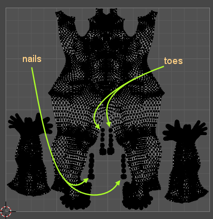
Now take a look at the UV Map. that seems to be wrong, no?
- The nails in the UV map are too big in relation to the upper body and the arms.
- The nails have overlapping parts with the body.
- Some nails are displayed somehow distorted in the UV map.
So, here is something to fix…
For the begin lets hide the upper body in the UV map and only keep the nails and toes visible:
- Hover the mouse over the Body in the 3D Viewport.
- press SHIFT ‘L’ to deselect the body.
- Do the same for the arms.
Now only the nails and toes remain visible in the 3D Viewport and in the UV map.

- Some vertices have been placed in the lower left corner of the UV-map, namely at location (0,0) those vertices have not been unwrapped.
- Some toes and nails overlap (see orange/pink areas in the image)
- Some U vertices are placed at odd places (see the spikes)
We take care of those issues one by one.
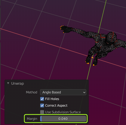
But before we take care of each UV vertex separately, lets renew the unwrap:
- press ‘u’ (for Unwrap)
- press ‘u’ again (for default unwrap)
- Open the Operator Redo panel (lower left corner of 3D Viewport)
- And play with the margin to separate the nails and tose in the UV Map
By now we have separated all parts nicely from each other. Now lets take care about the spikes.
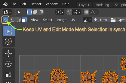
We can make this easier by synchronizing the selection on the UV Map with the selection on the 3D Viewport. But when you do that then all visible vertices are shown on the UV map and it looks rather messy. But we can fix that…
Tip: in the 3D Viewport press CTRL-I to invert the selection. Now all faces except the toes and nails are selected. Then press ‘h’ to hide all selected faces. Now you can only see the nails and toes in the 3D Viewport.
Press ‘a’ to select all nails and toes. Now you can see them all again in the UV Map.
The synchronization of the UV Map and the 3D View can be done in the UV section as shown on the image.
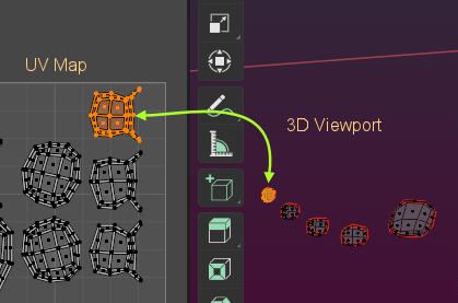
Now you can do a nice trick:
- LMB (left click) somewhere on the grey space outside of the UV map.
- hover the cursor over one UV island.
- press ‘L’ to select the island.
- Now the corresponding faces on the mesh are also selected.
- move the mouse into the 3D Viewport, then press the Dot (“.”) on the number pad.
- The selection comes into focus.
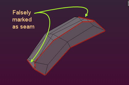
Now we can easily inspect the Mesh. And it becomes apparent what is wrong: We got an issue with the seams: Two edges are falsely(?) marked as seams.
- Select the two edges
- RMB – Clear Seam
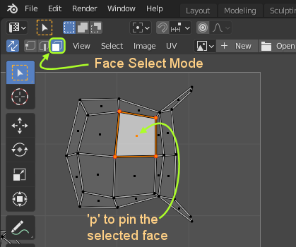
Now redo the unwrap (we use a trick here)
- Select one face of the toe
- press ‘p’ to pin the face in the UV map
This makes sure the unwrap remains at its location and it keeps the scale during unwrap. When you do not use this trick, then unwrapping one toe will use the entire UV-Map space. This is most probably not what you want.
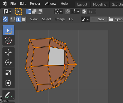
Finally we are ready to renew the unwrap of the toe:
- Select the entire toe-island in the UV map (press ‘L’).
- Press ‘u’ (unwrap)
- Press ‘u’ again (default unwrap)
Note: You also can make the unwrap of a toe a bit different, to separate the upper part of the nails from the lower part:
Instead of removing the seams we also could complete them (draw a seam from left to right) and unwrap again. This makes it easier to draw the part ‘under’ the nail. But at the end its your choice how to do the unwrap. Anything reasonable is permitted.
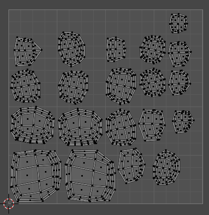
We can proceed with all toes and nails in the same way and clean their UV wrapping up.
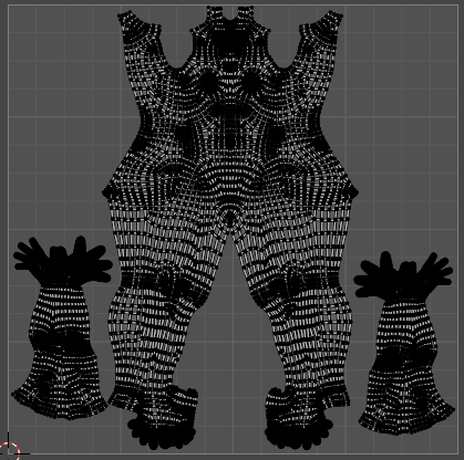
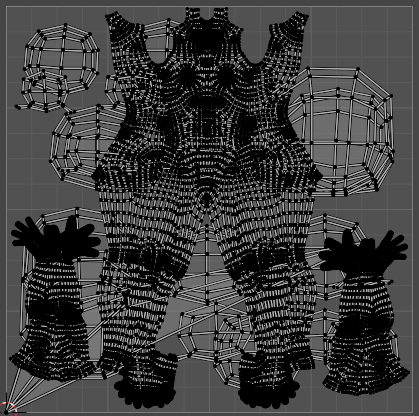
Here is the UV map of all toes and nails after fixing. However, there is a little caveat here, that is: The UV Map clearly overlaps with the UV Map of the body. So this is very bad, isn’t it ?
In fact it is not bad at all, the question is what you are trying to achieve here.
Let us elaborate on this and
- unhide all faces (press ALT-h)
- then select the body, the nails and the toes
- Press CTRL-I (lower case i) to select the rest of the mesh
- hide that (press ‘h’)
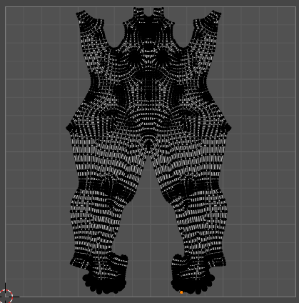
- And look at the U-map
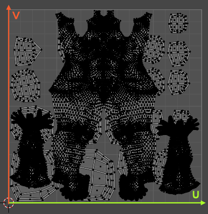
There are a few things to remember:
- What you see here is a map, this is not an image or a texture!
- A model can be setup with multiple textures using the same UV-map for different parts of the mesh.
- The assignment of textures to faces is done by use of Materials
So the UV map is not wrong so far. However, we use about the same map space for the 10 nails and toes as we use for the entire body. When we look at the difference of sizes of the nails compared to the size of the body we might ask our self if it is really necessary to have such a huge part of the UV map reserved for the nails.
As a consequence we find that a nail/toe texture can keep much more details as a body texture of the same size. If you need high details on the nails, then this may be what you want. But then you need to create two materials, one for the body and one for the nails&toes (although both can use the same UV map). then assign different textures to the materials.
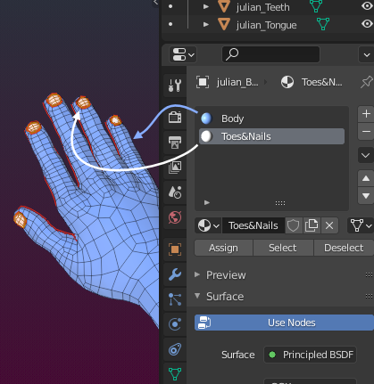
But if we wanted to use only one single texture (put the body and the nails&toes into the same texture), then we made a mistake. In that case we want to scale down the nails&toes and place them somewhere into the UV map.
We might actually want to keep the entire UV map clean and use much smaller UV ranges for the toes and nails and move them to a part of the UV map that is currently not used.
In this case we can texturize the body and the nails with one single texture.
Hint:
- Press ‘s’ to scale selected parts of the UV map
- Press ‘g’ to move selected parts around in the U map
- Press ‘r’ to rotate selected parts of the UV map
- You can temporary move parts out of the indicated UV-map range
Rearrange an entire map
Now that we have become a bit comfortable with the tool, here is a trick how you can speed up your work on the UV map. Lets assume you want to start with just one U map for the entire model and you want to rearrange this map for easy usage. Instead of inspecting the mesh and the map step by step we also can do this in one go. The workflow is this:
- make sure the entire mesh is visible
- Make sure you are in Face select mode
Repeat the next steps for each island until the UV Map is empty:
- Hover the mouse over any island on the UV map
- press l (lower case ‘L’) to select the island island
- move this island outside of the map
- press SHIFT-l (lower case ‘L’) to deselect all UV faces
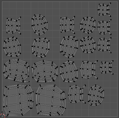
Now we can go ahead and select each isolated island and arrange it (move/scale/rotate) on the UV map in any way we want. And we can fix the mapping by selecting the island, pin one of its faces then unwrap the island again. We already know from the previous steps how all of this is done.
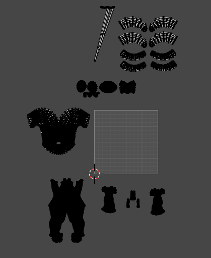
The final map could look like in the image aside.
Final note
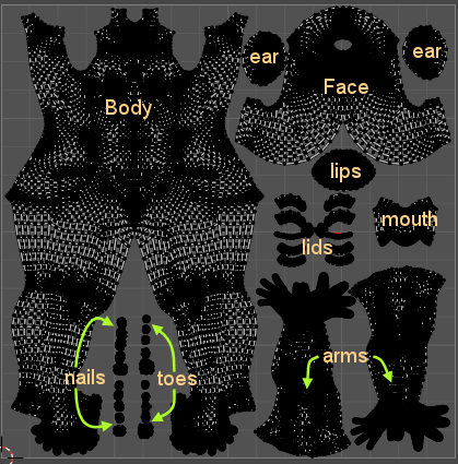
In most models it makes sense to use multiple materials to texturize your body. For example…
- You can scale up the face UV map to have more room for details, so you assign the related Mesh faces to a separate Face material.
- You may want to have more details on the nails? Scale up the nails U map and add a nails-material.
- You want to be able to replace lips color? separate the lips into a lips-material
And remember: Having overlapping UV Islands is not an error! You just need to use multiple materials for separating the parts.
I believe i have now talked enough about UV mapping. Now lets get into motion and …
Prepare the Rig
Now we have prepared our model as good as we could do. We can proceed by preparing the Rig. We will have to:
- Adjust the torso bones
- Adjust the hand bones
- Adjust the Face bones
We will Create a new Bento rig. We adjust the rig completely in Pose mode. Then we create a new Bind pose and use that for the final binding of the mesh to the rig.
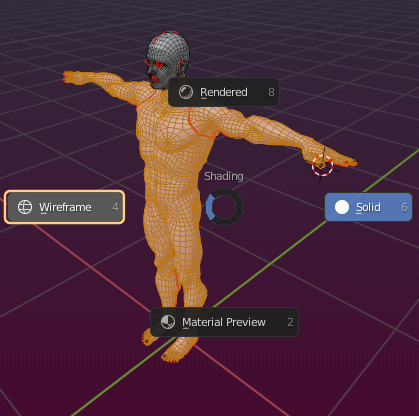
And we start simple by moving back to to the Layout Workspace and switch back from Wireframe mode to Solid mode (press ‘z’ and select Solid from the pie menu)
Note: Using poses to edit the mesh might first sound a bit odd, but you can see quickly why it actually is a good idea…
Create the Rig
We want to create a Bento rig. Actually we only need the Skeleton and the eyes from the Avastar character:
- Add – Avastar Extended
- open the N-Panel (Properties sidebar)
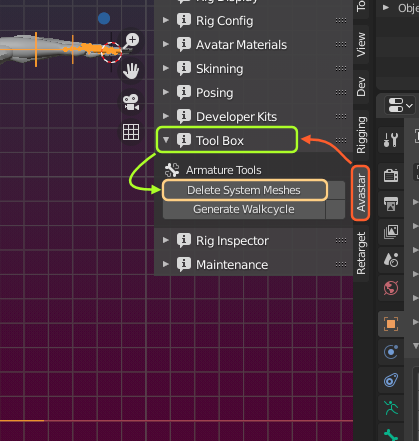
- Locate the Avastar Tool Box
- Delete System Meshes
Now all meshes are gone. But we have an Operator Redo Panel in the lower left corner of the 3D Viewport…
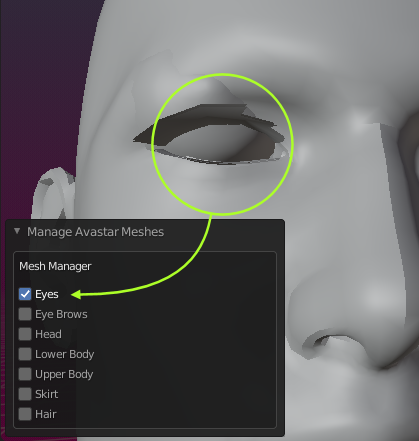
- Open the Operator Redo Panel
- Select the Eyes
Note: The eyes are not yet at the correct locations. We will take care of this later.
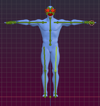
Now lets see what we have so far. Avastar by default creates female rigs. But of course it does support male characters too. There is a gender switch in the appearance sliders panel.
However it looks like this particular mesh was made for the Female Skeleton, because the Skeleton already matches so nicely without any modifications.
So we will keep the gender flag at female and only make some minor changes (see below).

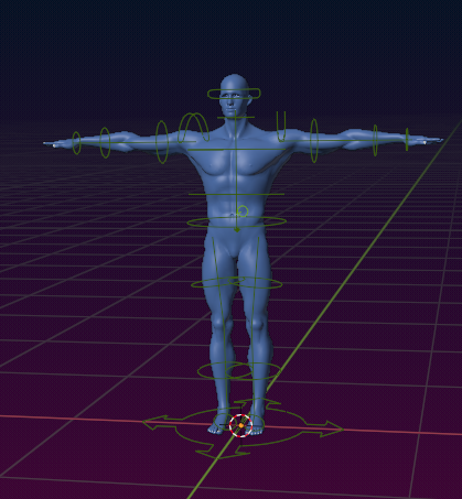
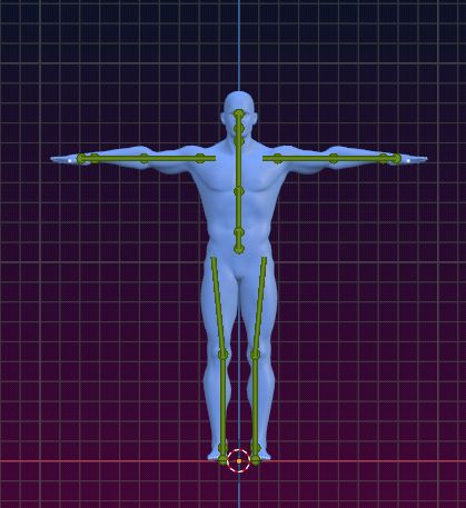
All following activities happen in pose mode. We will only use the green animation bones.
The torso bones
- We bend the hip bones by 3°.
- And we bend the Knee bones back by the same amount.
- That should be good enough for our purpose.
Tip: If the Knee bones can not be rotated you have to disable the rotation limits for those bones.
- Make sure you have the Knee Bones selected
- Open the Rig Controls Panel in the Rigging vertical Tab
- Click Disable Rotation Limits.

TODO: Rework below here
Arms and hands
- Open the appearance sliders
- Select the Torso section
- Adjust the arms length
- Adjust the shoulder width
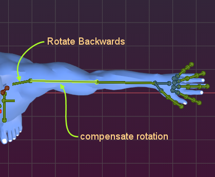
- rotate the collars backwards by about 6°
- compensate rotation on shoulders
- pose the hand bones
- also make the hands a bit bigger to change the distance of the knuckles

- Then pose the finger bones along the mesh fingers
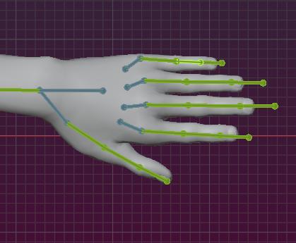
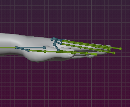
- Also take care that the fingers are oriented straight in side view
Warning: when you rotate the steel blue structure bones, then you introduce bone translation (moving) into the first finger bones. This possibly can lead to bending or even distortion of the fingers when you wear the mesh later in SL.
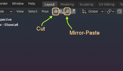
Tip: pose only one side of the character, then select all posed bones, and mirror copy the pose to the other side.
The Face bones
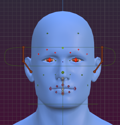
Before we start lets add texture to the eyes. This is very simple to do if the eyes are taken from the Avastar character (we did that further up in this document). Now we can get the eyes as follows:
- Select either the armature or both eye objects
- Set the Viewport Shading to Material Preview
- Open the Avatar Materials Panel
- Select Female
Now the character got the brown eyes from the Avastar.

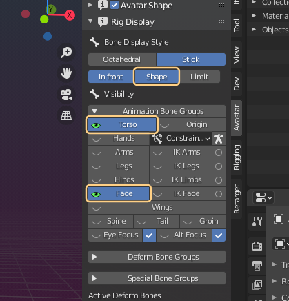
- Open the Rig display panel
- Enable the Face bones and the Torso bones
- Also make sure you have enabled Shape in the Bone Display style sections
Hint: Make sure you select the green Animation bone groups
The face bones obviously need to be adjusted to the mesh.
lets begin wioth the most obvious part – the eyes.
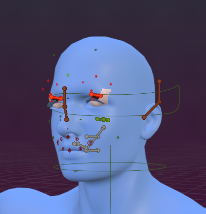
- go to side view
- Open the Appearance Sliders
- Select the Torso
- Use neck length to adjust eyes height in the head
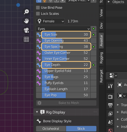
- Select the Eyes Section
- Adjust eye width, size and depth
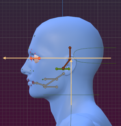
After the eyes are adjusted, you can proceed with the mouth bones. You do this best in side view…
- Select the Mouth Section
- adjust Mouth Position
- Select chin
- Adjust the Jaw jut
Adjust the various face sliders
- Open the Rig Display
- Switch Bone display to Octahedral
- Disable X Ray
- Adjust the sliders so that the bone tips are sitting close to the skin

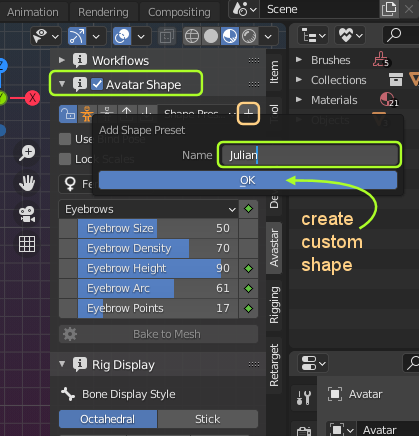
- Open the appearance sliders
- And create a new Shape Preset
Create the bind Pose
- Open the Posing Panel
- Locate the Rig Modify tools section
- As Bind Pose
This step has actually modified your Rig and now you got a couple of Joint positions defined. But…
You have created a Bind position. This gives you a great benefit. That is: You can later import your rigged meshes to SL only with weights. This makes the sliders behave much more predictable in the SL appearance editor.

Important note: the Bind Pose feature can only be used easily with human skeletons. For creatures or massively modified skeletons we need to take some extra action when we want to use bind pose. You can find more about this in the Bind pose documents.
Check the Bone Roll
There is a rule of thumb for the bone roll, that is:
- horizontal bones have their Z axis pointing upwards
- vertical bones have their X axis pointing Left
The reasoning behind this is that by convention the main rotation axis of a bone should be its x-axis. Because of this all finger bones have their x-axis laying flat while their Z axis points upwards. why? Because when you grab, then now all finger bones rotate around their local X axis… (for an exception see below)
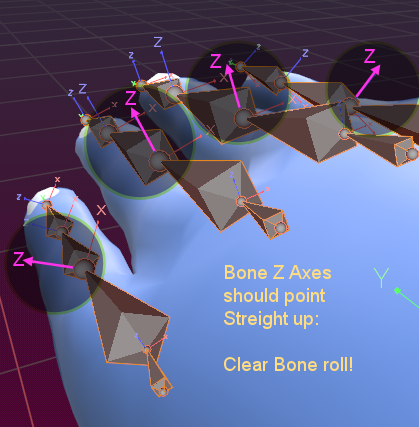
But our fingers have their local Z axis pointing anywhere but straight upwards. So we have to fix that now.
- Select the armature
- Make sure the green hand and finger bones are visible
- Go to Edit mode
- Select the finger bones and the Wrist bones
- Armature -> Bone Roll -> Clear Roll
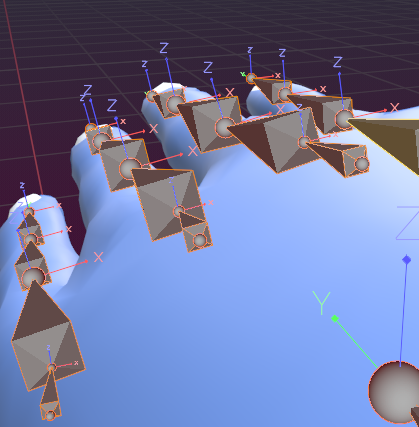
Now all finger bones have their local Z axis pointing upwards.
- Now select each bone of the Thumb one by one
- Then adjust the bone roll to 45 degree for the left hand
- And adjust the bone roll to -45 for the right hand

You might want to check also all other bones of your mesh for correct Bone roll. Now your rig is adjusted to the mesh and it is time for the final step, that is…
Bind the Mesh
- Select the Mesh
- SHIFT LMB the armature
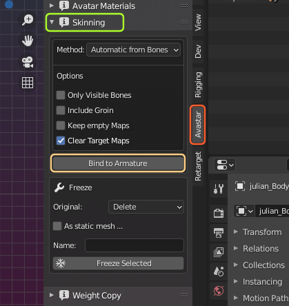
- Open the Skinning Panel
- Select the Bind Method as: ‘Automatic from Bones’
- Bind to Armature
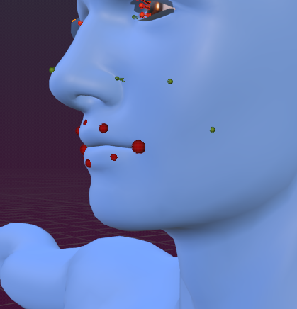
Now check the weights of your mesh by posing the armature and see if the skin behaves correct. You also can check if the apperance sliders now work nicely with your mesh. It looks pretty well now:
 If you look close to the head then you see that even the face appearance sliders are working, as the nose size has been changed using the Node – Size slider. The sliders work also in SL of course!
Make the Developer kit
- Make sure only one armature is in the scene.
- Make sure the Mesh is bound.
- Put mesh into Object mode.
- Put armature into pose mode.
- Put armature into restpose.
- Take care that you apply the previously stored character shape preset to your armature.
- Store this as a new blend file. This is YOUR reference file
Export as Collada file
Export the file with the Avastar Collada exporter as usual and test this Collada file with SL. make sure it uploads correctly to SL, it poses correctly and it just does exactly what you want it to do and how you want it to look alike in SL. If anything is wrong, then go back to the blend file and fix it until you are happy with the results.
Important: The Collada file is what you send to your customers as the Developerkit!
Configure (what your users do)
The next step must be performed by your users. You only need to deliver the just created Blend file to your customers. And you must tell them the customization parameters:
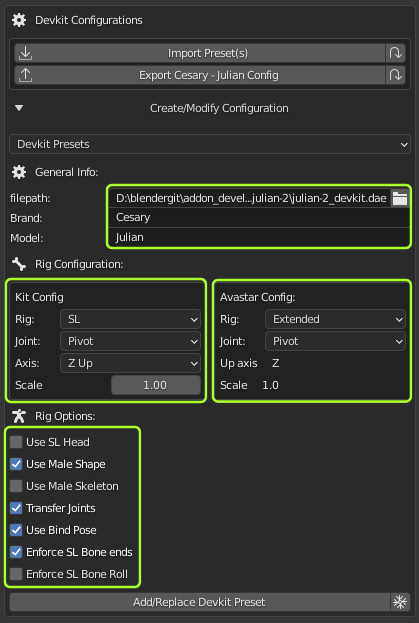
Import options:
- Brand (Cesary)
- Model (Julian)
- Imported Rigtype (SL)
- Imported Joint Type (Pivot)
- Imported Up Axis (Z Up)
- Scale factor (1.0)
- Exported Rig (Extended or Basic, user decision)
- Exported Joint type (Pivot)
Rig Options:
- Use SL Head (no)
- Use male Shape (Yes)
- Use Male Skeleton (No)
- Transfer Joints (yes)
- Use Bind Pose (yes)
- Enforce SL Bone Ends (yes)
- Enforce SL Bone Roll (does not matter its already correct)
And here is what your users will actually do with the above information:
Configure
- Open the Avastar Addon properties
- Locate the Developer kit Manager
- Setup the Developer kit parameters
- Add/Replace Devkit Preset
Avastar then stores your settings as a preset. This preset keeps available even when you update Avastar.
You can recall the preset fro editing in the Devkit Configurator, see Devkit Presets selection box above the General Info Section.
Use
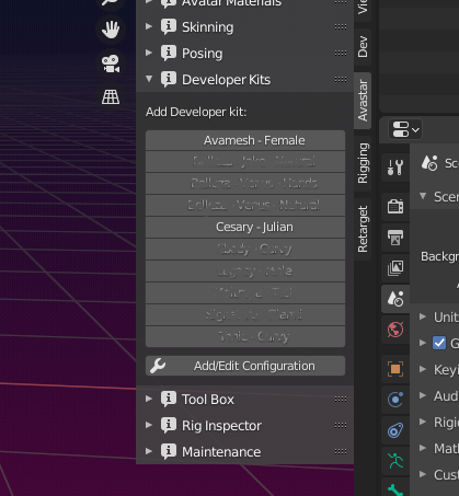
- Open Avastar – Developer kit Manager
- Select Cesary – Julian
Avastar loads the collada file and converts it into an avastar rig that is compatible with the current Avastar version.
Get Creative
Now go and make attachments…
I hope this document helps you to setup a fresh character and use it as your personal developer kit, or prepare it for distribution to your customers, whichever applies.
Feedback is very welcome.