Note: You find the Rigging a Horse video on youtube
The Video was made with Avastar-1
but is still mostly valid.
About this Document...
Content:
Create a Quadruped Rig (for a Horse)
The Video:
Editing the Avastar Skeleton into a Quadruped Skeleton
What does Avastar provide?
Avastar basically supports the creation of animatable Models (Avatars&attachments) and the creation of animations. Therefore the tool adds various functions and user interface elements to Blender.
The full functionality of Avastar can be a bit overwhelming on first sight. You should be prepared to spend some time and patience to get it all working nicely for your projects.
What does this Document provide?
This document is a quick start into Armature Editing. In this section you will learn how to prepare Avastar for your work on non human meshes. We use a Horse as the modelling example.
However this article only scratches the surface of Avastar’s feature set, so there is a lot more to detect and we invite you to make your own experiences as well.
We expect that you have basic knowledge about Blender.
Step 1: Prepare the scene
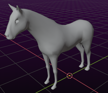
The Model
In this document we use a model of a horse made by the SL resident OptimoMaximo Resident as guideline for setting up the Rig. You may find similar models for example in the blendswap horse collection.
At the end of this document we will have a Rig that we then can use for binding almost any quadruped with only small adjustments.
Tip: In the next document about binding a quadruped we have chosen to use a spooky horse mesh (well, actually a skeleton) from neurocase at blendswap You can decide to use it right away or just follow this document by using any other quadruped you like. There shouldn’t be much variation in how to proceed.
More about the creator at www.dazpetty.com
Adding an Avastar Skeleton to the scene
So we expect you already have the mesh model in the scene and we do not need any Avatar meshes for our model. And although the Bento Skeleton already supports quadrupeds nicely, we have chosen to not use the Bento hinds for the begin:
Add -> Avastar -> Skeleton (for regular Avatar), or …
Add -> Avastar -> Animesh (for Animesh Avatar)
We will make a regular Horse Avatar, so we choose the Skeleton option.
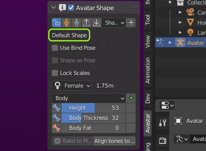
Note: If you later (in Secondlife) wear the Horse Avatar and you want to preserve the exact same shape as what you see in Blender then you also must wear the exact same shape in SL. So you must know this:
Of course you can decide to use any other shape in Blender, just need to use the same Shape also in Secondlife then.
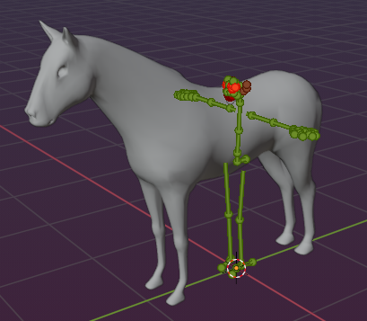
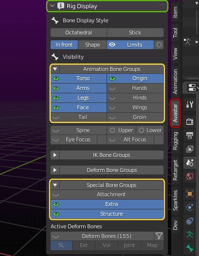
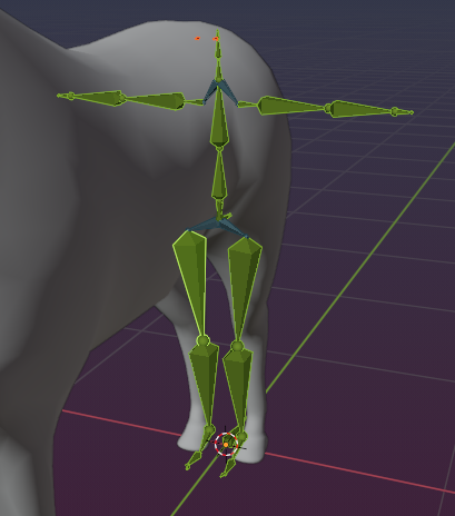
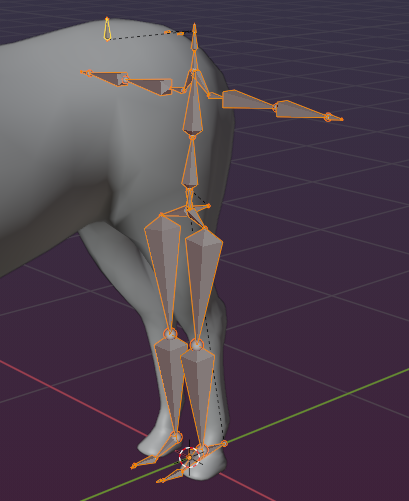
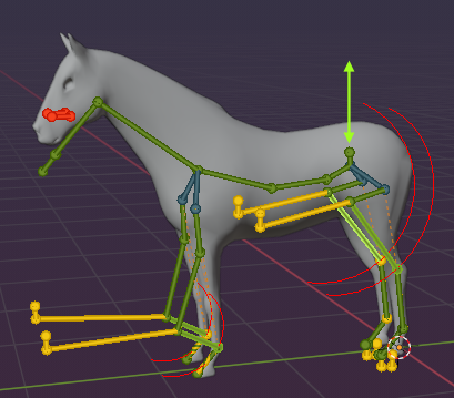
To see the exact same Skeleton as in the image above, you need to make sure that the Following Bone subsets are set to visible in the Rig Display:
- Torso
- Arms
- Legs
- Face
- Extra and Structure
Adjustements in Pose mode
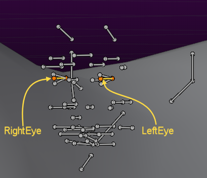
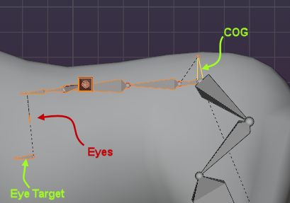
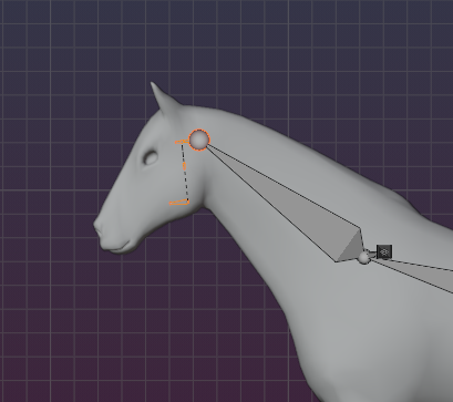
To keep it simple for now lets hide all face bones except the eyes. Of course this is just a proposal to begin with, you can keep the entire Face skeleton visible. And it is astonishingly complicated to get just the eyes. Anyways here is how it goes (the easy way):
But first of all i apologize that I now need to ask you to temporarily disable almost all bone groups which i just introduced above…
- Important: Make sure only the Face bone group in the Rig Display panel is enabled!
- Make sure that ALL other bone groups in the Rig Display Panel are disabled.
- Then select only the eyes from within the face
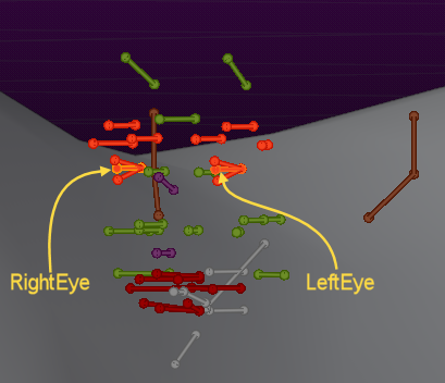
- Now press SHIFT h (hide all deselected pose bones). You should see only the two eye pose bones. Make sure you see EyeRight and EyeLeft
- Switch to EDIT mode (You will see all face bones again)
- Now press SHIFT h (hide all deselected edit bones)
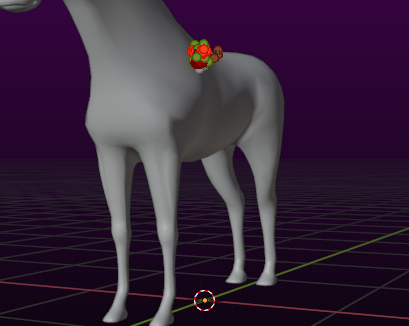
Finally step back to POSE mode, then select all bone groups that i have listed at the begin of this chapter.
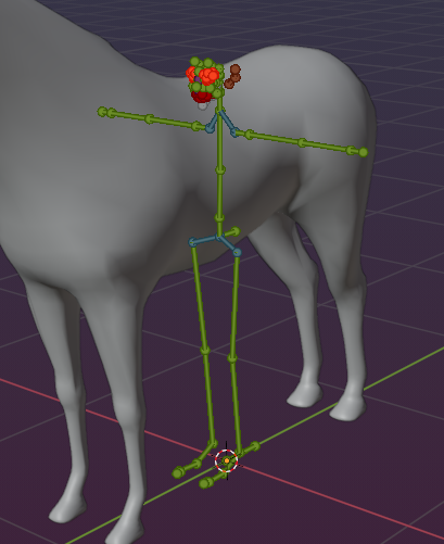
By now you only see the eye bones in the face and all other bones which we will need to convert the Rig into a veritable Horse rig.
Note: If you do this work for the first time then it might be a bit overwhelming first, but very soon you get accustomed to all of this. Just repeat things a few times and you see it becomes easier with time.
Note: We will not use the tail bones from the Bento rig, but there is nothing wrong to use them. We are sure you will manage to work with the tail bones after you mastered this tutorial.
While we are still in edit mode, lets enable the bone groups again (Torso, Arms, Legs, Face, Extra, Structure).
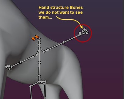
Note: You might see parts of the hand bones even when you not have selected the Hand bone group. If that happens to you, then open the Rig Display panel, and …
- Enable the hand bone group
- Disable the group again
This is a known issue in Avastar 3.0
Now lets get back to pose mode …
Some more Adjustments
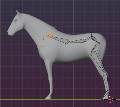
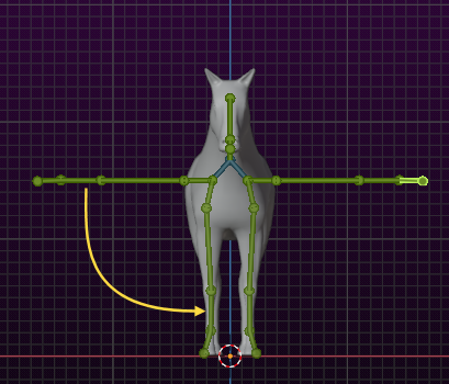
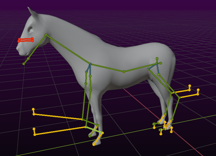
Recommended: While there is no strict rule to follow, we have chosen to keep the Rig Origin at the Center for simplicity and just move the horse in Object mode, so that the horse’s rear legs roughly match the Avastar legs.
I align the rear legs to the Avastar Ankle bones. (see further down for explanation)
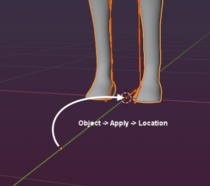
Please remember to move (in Object Mode!) the Horse Origin into the Center of the scene so that it matches with the Armature origin (not strictly necessary, but avoids pitfalls) (Object -> Apply -> Location)
If you can not select the Object, see below…
Nice Tip: You realized that you can not keep the armature in pose mode when you want to select the horse ? this is due to locked object modes. The idea behind this is that you only can select objects having the same mode than the active object.
In this case the armature is in POSE mode, the horse is in Object mode. So no way to select the horse…
Unless you disable object locking:
main menu -> Edit -> Disable Lock Object Modes
Or you can use a little shortcut that we added to Avastar, see image
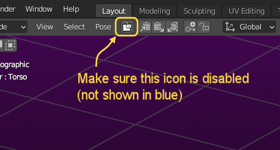
so now you can see immediately if Blender is in Lock Object mode or not.
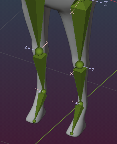
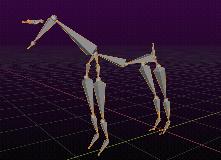
Optional: I like to use the Octahedral display of the bones for the next few steps. Again this is an option, you do not need to follow this proposal and keep with the default Stick Display. Here is how it goes:
- Select the Armature in Pose mode
- Open the Rig Display Panel
- Enable the Octahedral view
- Disable Shape view
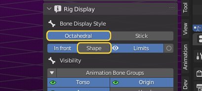
Your rig will now show all bones as asymmetrical octahedrals. This is just a display option, there is no change in functionality.
Step 2: Moving the bones into place
 Now we put the Armature into edit mode. Please use the Joint edit preset for this as it presets the Editor options for what comes next. You might want to disable the Display of the Hand bones (in the Rig Display Panel)
The Armature has now been switched to edit mode, bones are now grey with an orange outline when selected.
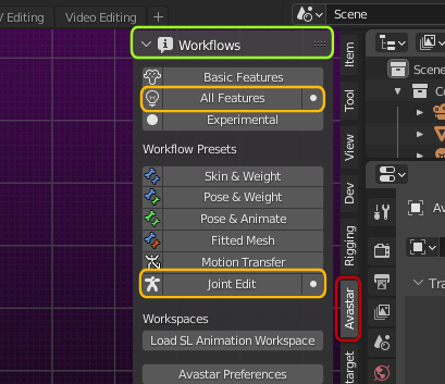
Note: When you edit a rig then you are an expert. So please make sure that you have enabled all features in the Workflow Panel, otherwise you will not be able to get your work done!
What the Joint Edit Preset does
- Make sure all (green) Animation Bone groups are enabled. Note: Blender does not use colored bones when editing, so “green” bones are actually displayed in grey like all bones in edit mode.
- Face and hand bone groups are also enabled automatically, so you need to adjust the rig display panel if you do not need those bone groups in your rig.
- Show the structure bones and make them editable.
Note: Structure bones are mostly useful for animation, You normally do not want to edit them directly. However, it is easier to edit the other parts of rig when the structure bones are set to editable.
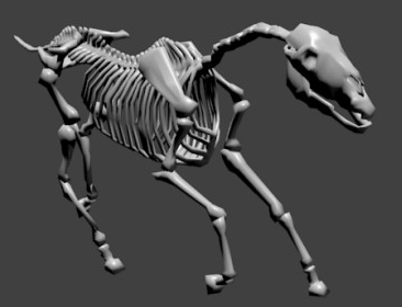
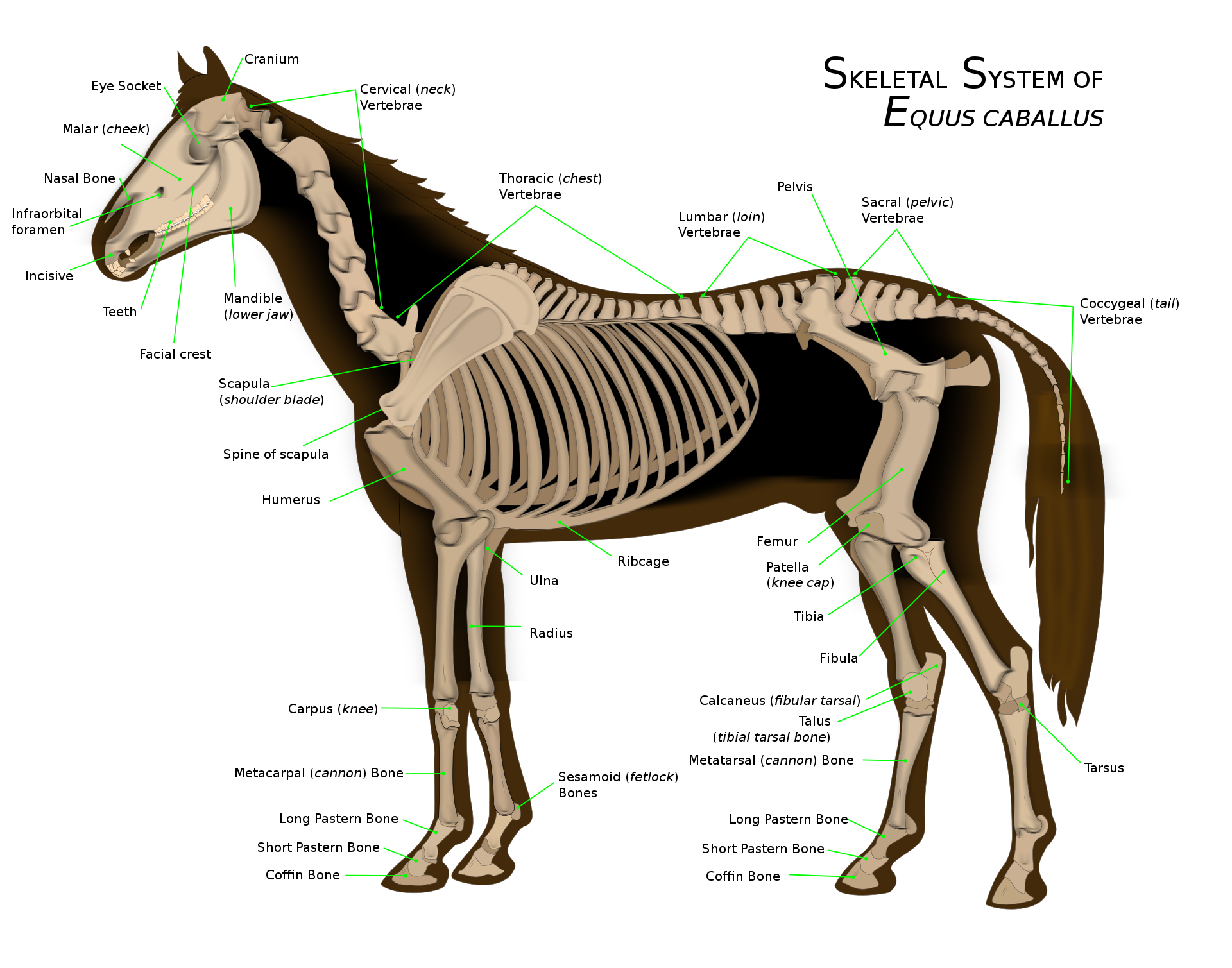
before we can place the bones we should get a rough idea about the general structure of a horse skeleton. You find more details in Wikipedia – Skeletal system of the horse
We only have a limited set of bones available in Secondlife and we also are forced to reuse the Secondlife bone hierarchy. So we have to be a bit creative here.
Click to zoom in
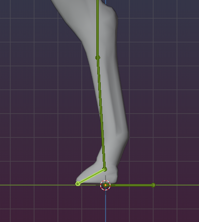
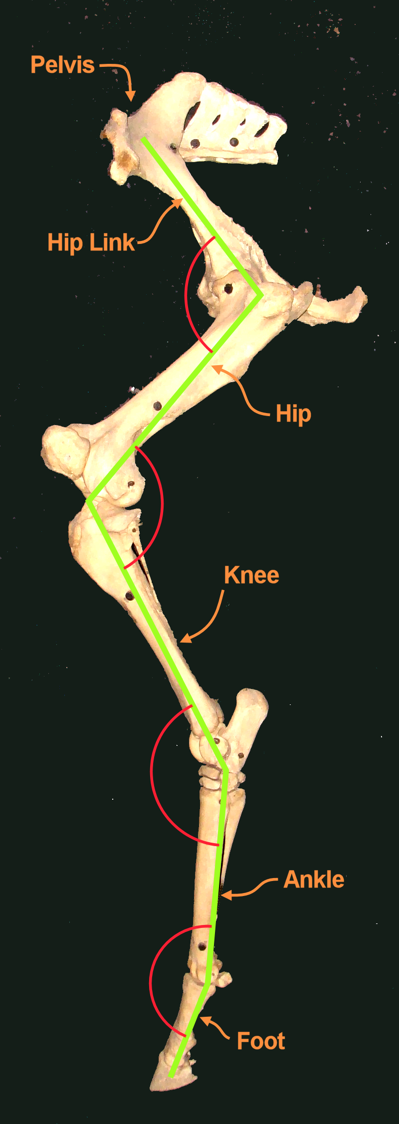
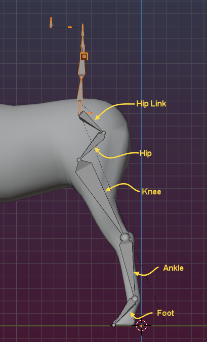
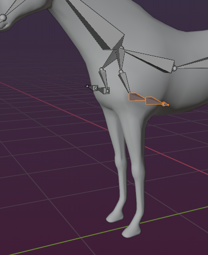
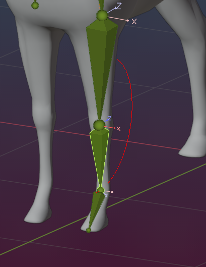
Lets take a look at the horse’s rear legs. I added a green line indicating where our bones will be located. I added labels (orange) for which bones we will use and i added rotation angels (in red) to indicate how the bones bend.
You see the legs work quiet a bit different from a human rig. However we can also see that the human bone hierarchy can actually be reused. But note: We will later see that we have to reorganize the IK bones as they have to use very different constraints than we have defined in the default Avastar character .
Lets begin with the Foot bone and work our way up until we reach the Pelvis (and COG) bone.

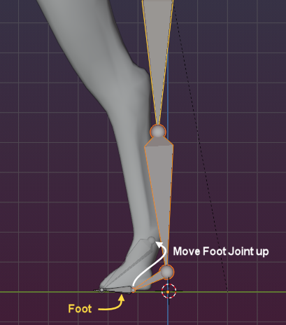
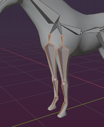
Now select select the entire skeleton except the toes and the foot bones. we will move the bones all together, this way you avoid some messy situations while moving the bones. Now and move the joints all up as seen in the image.
We can now move upwards along the horse legs and adjust the bones as needed, always selecting just the bone tips as you did for the ankle bones (see above) until we reach the COG Bone.
Important: From now on you need to be careful with the X-mirror setting that i proposed further up. If bones start to move in odd ways while you drag them around, then maybe X-Mirror does unexpected things for you. In that case you better turn it off again.
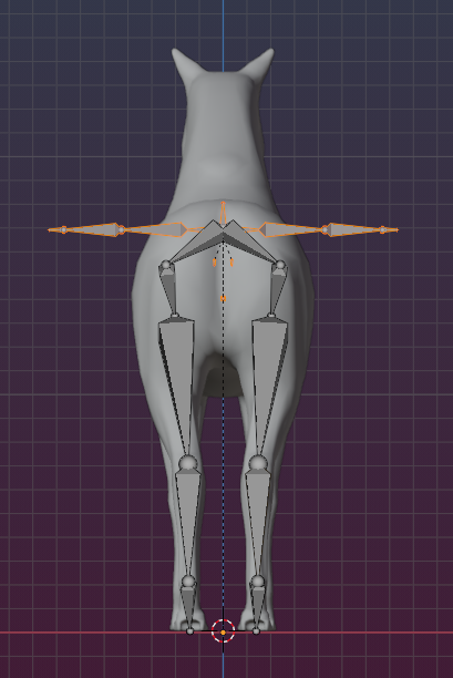
We also need to adjust the joints from the backside view CTRL Numpad 1)… This is where we can make use of the X-mirror tool as we can work on one side while the other side gets auto adjusted
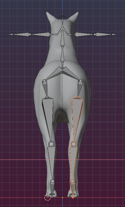
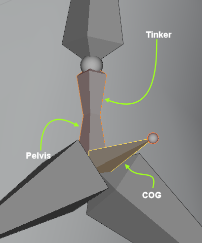
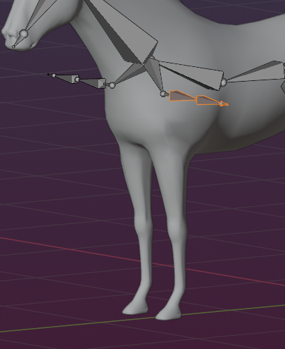
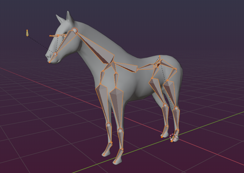
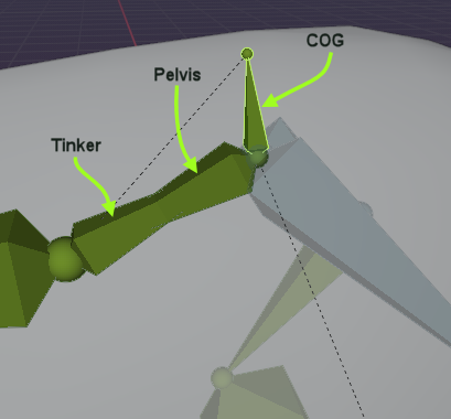
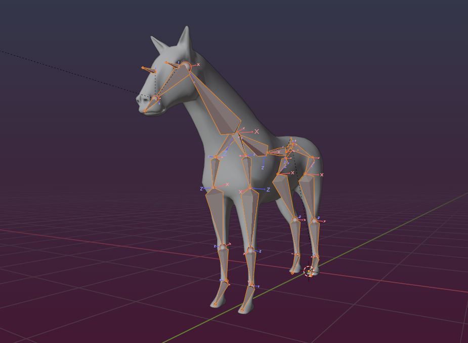
Please select all bones of the head and upper body including COG, Pelvis and Tinker as indicated in the image.
Then lets take a closer look at the pelvis bone. Actually you see 2 pelvis bones here: The Pelvis and the Tinker created in opposite directions.
Some important notes:
- We recommend to keep these 2 bones aligned to each other as they are!
- You can edit the COG Bone rotation and tail location as well, but be aware that the COG bone is automatically moved to the same location as the Pelvis Head!
- You can edit the structure bones, but please be aware that Avastar always replaces those bones such that the structure bone head is located at the Pelvis head and the structure bone tail is located at the Hip Head.
Now move the bones upward and rotate them all by 90 degrees as indicated in the images below. The currently selected bones will be used for the entire front of the horse as we show in the next steps.
Tip: When you select the COG as the last bone (making the COG the active bone) then you can configure that rotations use the active bone as pivot. This make your positioning a bit easier.
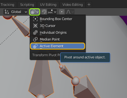
The active element is always displayed in a brighter color as all other items. If the COG is not the active element, but it is selected, then SHIFT LMB (click) on it to deselect it, then SHIFT click again. Now it is selected and the active element.
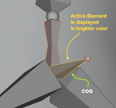
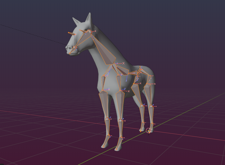
This is the skeleton after the upper part is rotated by ~90 degree around the COG Pivot point. The COG now points straight upwards and the triple (COG,Pelvis,Tinker) kept their relative orientation to each other as recommended.
The following series of images shows the progress of the editing.
Finish the Rig editing, shown with Images
13
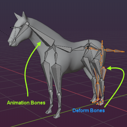
Step 3: Adjust the Deform Rig
Important: By now we only have edited the animation Rig (green bones). But Avastar contains also a Deform Rig (blue/purple bones).
However, since we have not yet touched the deform rig, it still has all its bones in the default locations.
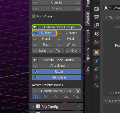
You can make the deform rig visible from within the Rig Display panel:
- Open the Deform Bone Groups section
- Enable SL Base
Now the deform bones show up in the 3D Viewport.
So what to do with the deform bones ? Simply ignore them!
Avastar will take care!
What? …
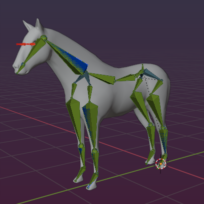
Yes, Avastar knows what to do with the deform bones. Just let it do its job and do not worry, at least for now. We come back to the deform bones later when it comes to Binding and skinning.You do not believe this? Make the test: Switch from Edit Mode to Pose Mode and see what happens.
You see the deform bones have been positioned automatically to match the Animation bones. You still do not believe me? …
Then proceed as follows:
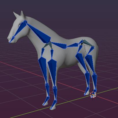
- Open the Rig Display panel
- Hide the Animation bones (Torso, Arms, legs, …)
You end up with seeing only the blue deform Rig. So you verified that he deform bones have been automatic put into the correct places. Now you can hide the blue deform rig again, we do not need it for now.
Keep with the green bones!
Make sure that you have kept Pelvis and Tinker (PelvisInv in older Avastar versions) perfectly aligned to each other. If you fail to do that, then switching to Pose mode might give unexpected results!
Step 4: Adjust the Rig for proper use
By now we have put the bones into place. However, there are a few issues with the rig. The problem is those issues are not obvious. The rig as it is might even work already for making rigged mesh and if you are lucky, your exports to Secondlife will work as expected.
But more often than not you will face more or less serious issues, which all are related to various little caveats. So we need to talk about those quirks and oddities, how to find them and how to fight them…
Adjust the Bone Roll
Remember, the front legs of the Horse have been bent downwards by 90 degree to change them into the front legs of the horse.
The bone orientations are now messed up, especially the local bone X-axes and Z-axes are not consistent. Actually we want to follow a convention, namely we want bone X-axes either point forward along the global X-axis or we want the bone Z-axes all point upwards along the global Z-axis.
This convention seems to have been established when the BVH animation format was invented. And Secondlife seems to also use this convention for its mesh imports.
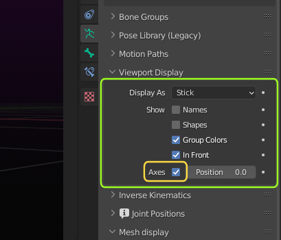
This issue is directly related to the Bone roll (the relative rotation of bones along their local Y-axes). Note that we might end up with serious distortions on the meshes after uploading to SL. And luckily we have a very convenient cleanup function to fix the Bone Roll. But lets first enable the display of the Bone axes:

- Enable axes in the object data properties (Viewport Display Panel),
just to see what happens next.
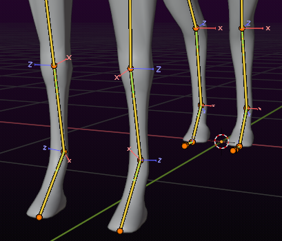
- Switch the Armature to Edit Mode
- Select all Bones
when you look at the rear legs, you see all bones x-axes are oriented towards the global x-axis as wanted. But the front legs are a mess.
The good new is: Blender has an easy fix for you:
- Make sure that all animation bones (the green ones) are visible and selected.
- Armature -> Bone Roll -> Clear Roll ( shortcut: ALT R)
Now all bones should either have their X-axes oriented towards global X or their Z-axes oriented towards global Z. Note: This works best when bones are placed vertically or horizontally.
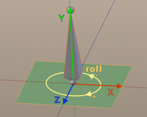
What is Bone Roll?
In simple words this is the rotation of a bone relative to its long axis (see image).
The main problem that we have here is: We do not have a way to find out where Boneroll = 0 is. The Blender Operator ALT R (Clear Bone Roll) actually resets the bone roll to 0 and rotates the bone(s) so that the Octahedral representation is aligned to the local coordinate system.
Adjust the Bone Rotation limits
The original Avastar rig comes along with a set of rotation limitations, such that the skeleton can not be animated into awkward poses.
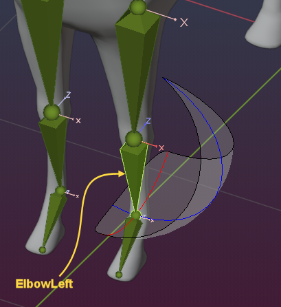
However, we now have edited bone locations, so the bone limits may no longer be correct. We might need to change them. You see for the Elbows that the limits are somewhat misaligned by 90 degrees. We will change that now.
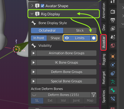
Pitfall alert: There are two locations where we can change the rotation limits and we need to change them both. But lets first enable visibility of the bone limits:
- Open the Rig Display Panel
- Enable visibility of Bone rotation Limits
- Also enable the limits (white bullet, see image)
Now select one of the Elbow bones in Pose mode.
Change inverse kinematic constraints
This is the easy change because you get direct feedback in the viewport.
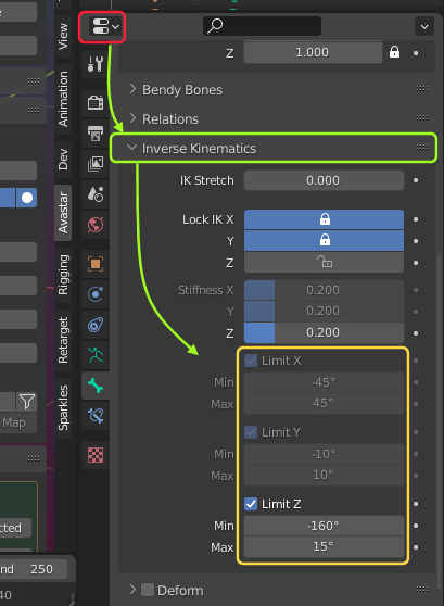
- Open the Bone Data properties
- Inverse Kinematics subsection
Now focus on the Limits settings and ignore they are greyed out. You still can edit them.
When you look carefully at the Elbow constraints in the Viewport, you see the values for the X limits and Z limits need to be exchanged. But when you simply exchange the values, you will see two issues.
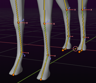
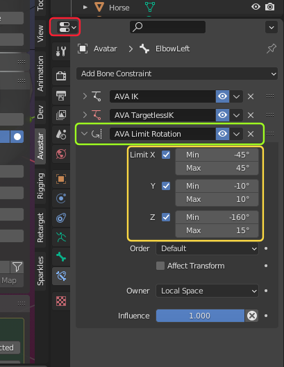
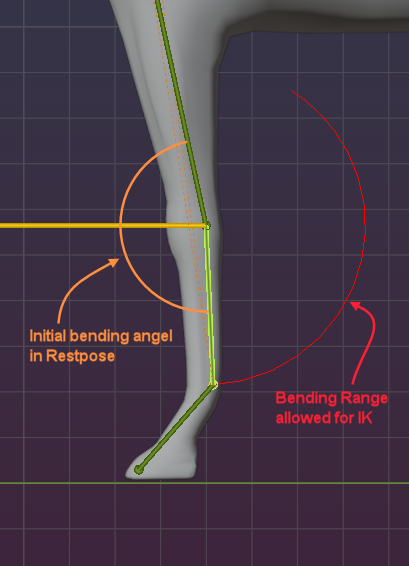
Look at the blue trajectory in the image for rotations along the bone’s local Z axis. The trajectory shows where the bone tail may be located while rotating.
We might want to restrict the rotation to very few degrees only or even better disallow any rotation in that direction. Actually we can disable rotations on the Z-axis all together, since horses can not do this rotation at all!
Look at the red trajectory for rotations along the bone’s local X axis: When examining carefully we realize the bone needs to bend into exactly the opposite direction! we need to fix the numbers.
After some experimentation i ended up with:
- X-Axis: -10 to +145 degree
- Y-Axis: -10 to +10 (unchanged)
- Z-Axis: 0 to 0
However, when you now try to rotate the bone, you see it does not take care of the just defined inverse kinematic limits (because we have not enabled inverse kinematic at this moment).
Actually you also need to copy those limits to another place, that is to the Elbow bone constraints…
Change the Bone rotation constraints
We have added a Limit rotation constraint that applies when you move the bone directly, opposed to IK where the bones are rotated and moved depending on the IK rig (more see below)
- Open the Bone constraint properties
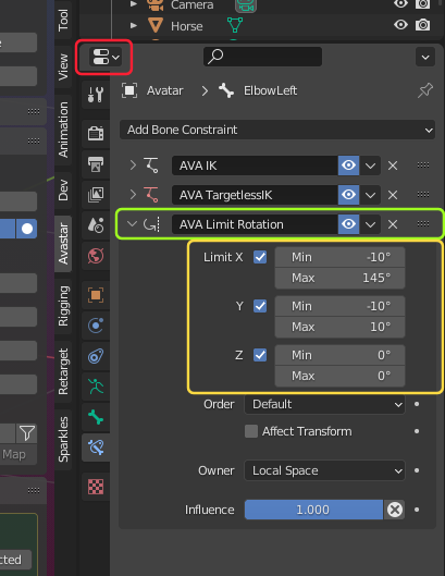
- Locate the AVA Limit Rotation constraint
- Check the limits
You see the limits in this constraint are exactly the same as we found in the inverse kinematic section.
Lets change the limit settings exactly as we did for the inverse kinematic:
- X-Axis: -10 to +145 degree
- Y-Axis: -10 to +10 (unchanged)
- Z-Axis: 0 to 0
From now on the bone can only be rotated along its own local x-axis (because of the constraints) and when using inverse kinematic, the same limits apply (see above)
Please do not forget to make the same changes on the opposite Elbow bone. Then the rotation limits are fully defined.
Step 5: Adjust the IK
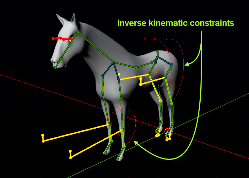
Remember that we have reshaped the human (Avastar-) Skeleton into a Horse skeleton. Now it is time to check if the related IK Rig is still valid and works as expected. So lets first inspect the IK rig as it is now:
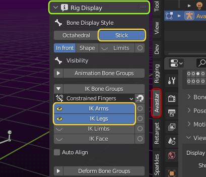
- Enable the IK Bones in the Rig Display Panel.
- Switch from Octahedral to Stick Display style
Note:If you have X Mirror still enabled (see above):
Then make sure that you select only one of the IKTarget bones at a time. the symmetric bone will follow anyways.
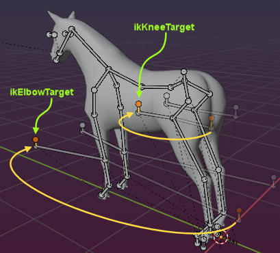
Now enter edit mode and locate the IK Target bones. A quick inspection shows the Target bones are located at the wrong side of the limbs. This happened because we have moved the related animation bones (Elbows and Knees) to very different locations on the rig. So we now have to adjust the targets as well:
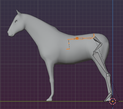
- Move ikElbowTarget(Left,Right) to the front of the horse’s front legs
- Move ikKneeTarget(Left,Right) to the front of the horse’s rear legs.
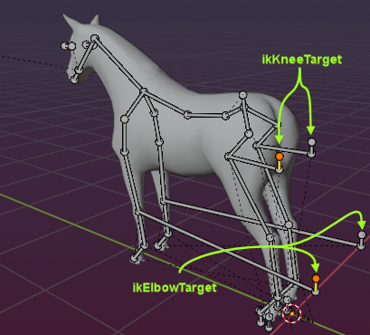
ik Target Bones after moving into position
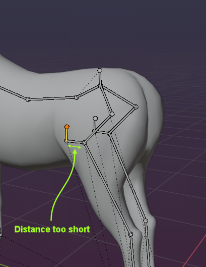
Tip: The Targets must be moved at least so far away from the related bones, that the connecting bones between the target and the limb never flip over to the other side of the Target bone while animating. Otherwise the related bones will do crazy things when animated.
Now its time to switch to Pose mode to make the final adjustments for the Rig…
Step 6: Testing and final adjustments
Switching to Pose mode should now only change the colors of the bones but not their position:
If you see positional changes of the Bones then go back to the previous chapters and check:
- Pole Targets are on the correct side of the limbs
- Pole targets are far enough from the related bones
- The bone rotation limits are set up correct (and are displayed on the correct side of the bones)
Is the initial rotation angle of the related animation bones correct?
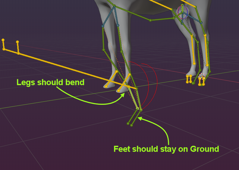
So when you now move the COG bone downwards, then the horse legs move while the hooves should stay on ground. However, if you move the COG too far, then the legs will start doing crazy stuff, simply because the bone lengths can not be changed, while the IK constraints try to move the bones into impossible poses. So the bones step out sideways.
If your Rig behaves in the same way, then you have managed to create a working quadruped Rig with IK support. However, sometimes the IK Rig seems to be broken although you took great care of everything and it just won’t work.
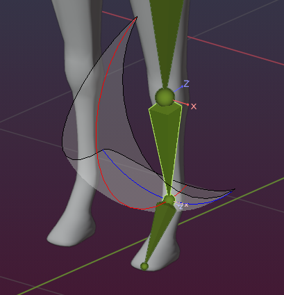
In the image you see the front legs won’t stay at ground level and they not even bend when you move the COG downwards. And yo made sure the IK is enabled…
The problem here is that the related bones (ElbowLeft and ShoulderLeft in this case) are rotated in Rest pose. But the rotation does not match with the allowed rotation range for the Elbow bone in the inverse kinematic constraints.
Hence the IK resolver is not able to calculate any transition from the rest pose to the IK pose. So it does nothing, the bones do not bend. And since they can not change their lengths they sink into the ground instead.
What we need to do is change the rest pose such that the initial rotation of the Elbow relative to the Shoulder goes to the other side.
Now the initial rotation angle is on the same side as the Inverse Kinematic angle (see image above)
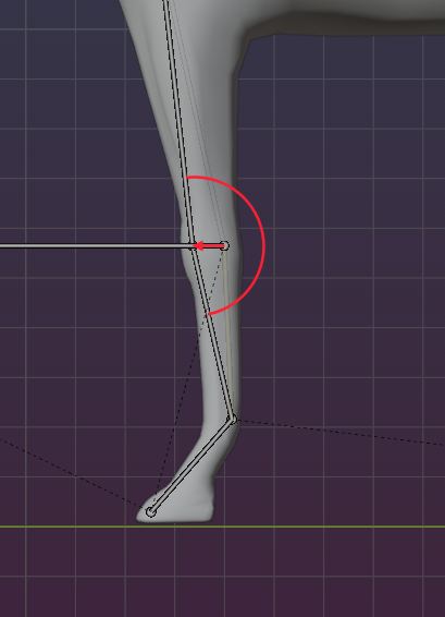
And finally we have done it, the Rig works as expected.
Note: Until here the Horse mesh has not yet been bound to the Rig. that is why it does not move along when we animate the rig. But no worries, the binding of a mesh to a rig will be described in detail in the Bind a Creature document.
Make the Rig reusable
Our goal is to have a Rig that can be reused for many different Quadrupeds. So in the final step we
- remove the Mesh
- Put the armature into its rest pose
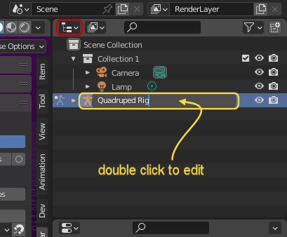
- Rename the armature from Avatar to Quadruped Rig
- switch to Object mode
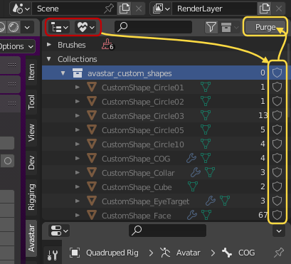
- In the Outliner open the Orphan Data section
- Open the avastar_custom_shapes collection
- remove all Fake user flags (shield icons, see image)
- Now click purge several times until no more orphans are visible except the Blender Brushes
- step back to Object mode
- Store the blend file into a convenient place
Whenever you want to start a new project with a Quadruped rig, then you now can File -> Append your just created Rig into your scene. So…
Mischief accomplished!
Now we are ready for the next task: We will bind our creature (Horse, dog, sheep, Elephant, tiger, …) to the rig
Trouble Shooting
My Rig bends in wrong direction
I have setup my Rig with all constraints fixed. But still the limbs bend in the wrong direction. How can i fix that?
When the constraints are set correctly or when there are no constraints set at all, then the IK resolver still can get into trouble when the rest pose angle between 2 bones is setup in the wrong direction.
In the example image the angle between the Elbow bone and its parent bone (shoulder) is set too far to the right. In this case the IK Resolver tries to move the joint backward when the COG bone is moved downward. But the Rig creator actually has expected the joint to move forward in this situation.
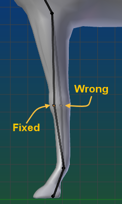
The fix is indicated in the image: Just move the joint a bit so that the angle betwenn the two bones opens in the opposite direction.