Chapter II: Create the basic shoe shape
- I will use the Grease Pencil to point out where i want to have extra edges and more or less face density.
- I will construct a very basic 3D box model for our shoe.
- I will introduce the mirror modifier and explain some quirks about vertex poles and face loops.
Hint: It is not essentially necessary, but maybe helpfull to also watch the previous part of this tutorial series.
Step I
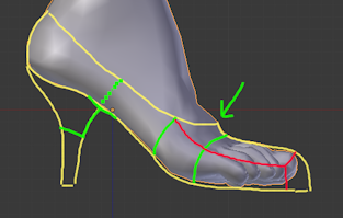
We start with a rough sketch of our shoe. You could just search the internet for a side view of your preferred shoe model and use that. But i have already used Blender’s Grease-pencil to sketch my shoe directly on the screen. And i used my character model from Make Human as my foot reference.
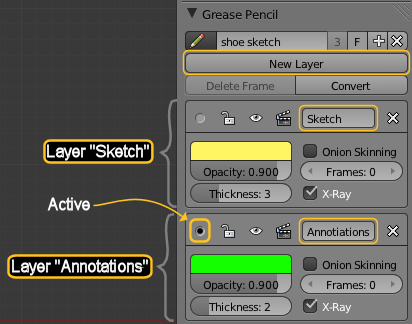 Before we actually start with modelling, let us first take a closer look at the sketch.
- For this purpose i add a “New Layer “,
- which i name “Annotations”
- and colorise it in green.
The layer is automatially selected as “active layer”, hence as soon as i start using the grease pencil, all i sketch will be painted in green.
Hint: a nice way to activate draw mode is by pressing the “d” key and keep it pressed all the time while you use your mouse to draw (press LMB), or erase (Press RMB)
Hint: Paint straight lines by pressing down the CTRL key while you draw.
Hint: When you use the above described method, then please ensure that the checkmark for “Use Sketching Session” is disabled. Otherwise you can not erase with CTRL+d+RMB
Step II
When you create 3D models, then you will use “Polygons” as your atomic elements. These Polygons get attached together to form your final shape. Amongst all possible polygons, you will mostly use Triangles (Tris) and Rectangles (Quads) for your work. Many 3D-tools do not even support other polygon types at all. And many (most? all?) game engines will convert all polygons to triangles before they actually use the models.
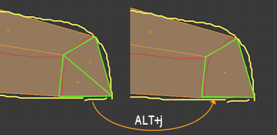
And there is another nasty caveat here: A Quad can be converted to a Triangle in 2 ways, see image above. And this can have an influence on the actual display of your model due to lighting calculations along the triangle edges.
Hint: Blender will eventually support polygons of arbitrary edge count (b-meshes). The release of b-meshes is planned for end of 2011.
Now there are some ongoing discussions about when you should use Tris and when you should use Quads in your model. The most important issues with this are related to texturing and animation. And during modelling you will face more problems with Triangles than with Quads especially when you plan to use the “Subdivision Modifier” for your work. Here are some issues with Triangles in your Model:
- Using triangles in your model tends to not work well with subdivision.
- Triangles break edge loops. That is bad when you try to optimize your mesh (reduce polygon count).
- Triangles tend to create much more complex mesh topologies. While easier mesh topologies can be maintained with less work.
So whatever you create, it will be converted into a triangulated mesh upon import to the target system. Hence it makes a lot of sense to learn how you can use triangles for optimization purposes. I might later prepare a separate tutorial “The secrets of Tris & Quads” at some time in the future.
 For now our guideline will be:
- Use Quads as much as possible while you are in the modelling stage.
- Use Tris where using Quads would make your model more complicated.
- Use Tris when they help to optimize your mesh in the Optimization stage.
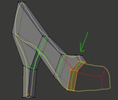
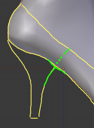
So keeping this in mind, we will take a first look at our shoe. And we will concentrate on the top of the heel, where it joins the sole. There you see 3 lines coming together and forming a “T” shape.
T-shapes are locations where you will be tempted to use Tris. But in many cases you can avoid that by just “completing the broken edge” as i have sketched in the image to the right (look at the green dotted line).
Now take your own pump (if you have one at hand) and check how the cobbler has solved this issue. You often will find that shoes do add a seam exactly where we added the extra edge. Though the edge may flow with slight variation, for example it may be bended more or less, it may go straight upwards, or even backwards….
I will also add another edge right in the middle of the heel, because its backpart needs some bending.
Now let us check the front part. Here we see that our model needs some bending. But bending can only be done along edges. Hence we will have to add at least one edge here. But when looking at the place indicated by the arrow, we already can imagine that something will happen there.
It may be not obvious, but we will see later, that we will go along the way i sketched in red (i silently added another Grease pencil layer). Just take another look at your shoe. You might find a seam there too. Well, maybe not in your pump though…
The shoe tip is not a complicated part either. We can (for now) just neglect the smooth bending which we certainly desire for our model. That will be fixed later when we refine the model.
Step III
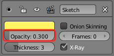 And now we are very well prepared to create our Box modell. We can reduce the opacity of the grease pencil layers. That helps us to actually see, what we are doing when we create the model.
And because our modelling method is named “Box Modelling”, all starts with a cube… That sounds familiar, doesn’t it ?
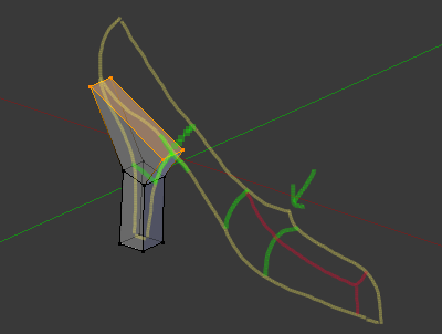
- Create a mesh cube and scale it down by a factor of 100 (use “s 0.01”). By now the sketch has disapeared.
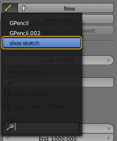
- Open the Properties panel (press “n” on the keybord) and from the Grease Pencil section select your grease pencil from before. I have named it “Shoe Sketch” to better locate it in the list.
- Now click anywhere into the 3D view and our beloved sketch reappears.
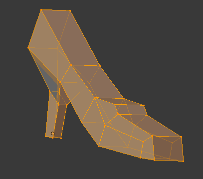
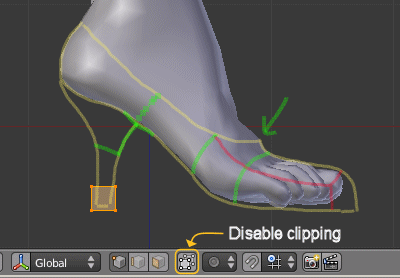 Hint: I always extrude complete planes. This ensures that i only create Quads. Therefore i have disabled clipping:
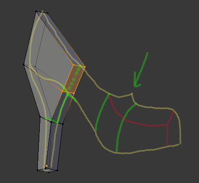
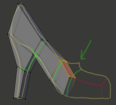 Here we are actually splitting up our flow. I first extrude upwards, and then (see next image) i extrude 2 faces
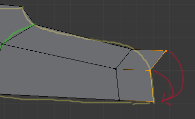 And a last extrude to close the tip. Note that i have collapsed the 2 upper vertices into the vertex at the bottom (see red arrows) So i end up with 2 (actuall 4, remind the other side of the shoe is currently not visible) triangles
Step IV
- We only need to move one half of the vertices.
- We can not break the symmetry. The modifier will not allow that.
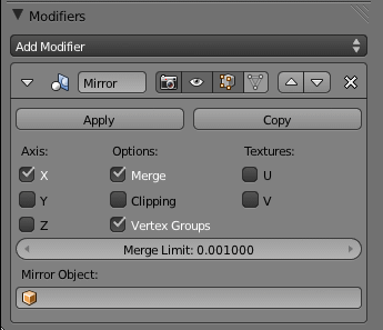
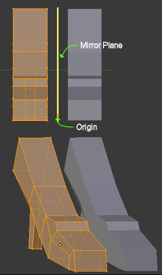
- Axis: The modifier can be customized to mirror along any combination of axes. Right now it mirrors along X-axis which means the mirror is placed on the Y-Z axis. Note that the mirror plane is fixed at the Object Origin in 3D space. We will see in a minute what that means.
- Merge: The modifier creates one mirror vertex for each vertex in the model. This is also true for vertices which are located exactly on the mirror plane. In this case the vertices get duplicated. If you do not want that (which is in most cases), you will check the Merge option. This will remove doubles on the mirror plane.
- Clipping: You can move vertices all around the 3D space. You also can move a vertex through the mirror plane on the other side. If you check Clipping, then the mirror plane will become a hard barrier and you no longer can move vertices through it.
- I skip over the remaining parameters because we do not use them for now.
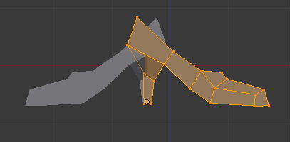 So let us see what the mirror modifier did to our object. The grey part is the mirrored part. We will see further down how we also can show the mirrored vertices. We first have to fix something. Mirroring along the X-axis is not what we want. Our mirror axis is apparently Y. So lets change the mirror axis from X to Y in the modifier.
 the mirrored part ? Lets go to side view and see where the object Origin is located.
Do you remember what i wrote about the mirror plane ?
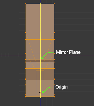 It is fixed to the object origin. Hence right now the object is mirrored exactly into itself. So lets move all vertices along the Y-axis and see what happens…
And this is where clipping comes into play. When we enable clipping now, then move the selected vertices back towards the grey (mirrored part), then when both parts touch, you will see that the moved vertices do not move further than up to the mirror plane. Now continue the move until also the heel parts touch.
 When we now stop moving, then try to move again, we see that the vertices on the mirror plane no longer move away as if they had been glued to the plane. Remember that we have enabled “Merge” by default. And that means the duplicate vertices on the mirror plane will be merged and thus we end up with one single mesh.
But hold on, there is still something wrong here. When you look closer then you see that some vertices and edges now are located inside the shoe. This is very bad and if we do not fix that immediately we will later get a ton of problems with our face normals and with crazy artefacts during texturing.
General Rule: Never accept vertices, edges or faces INSIDE a closed mesh. There may be exceptions though (as always) but you really should take care to avoid this situation at all.
Now how to fix that ?
 First lets us hide the mirrored part, so that we can get better access to the bad vertices. We can do that in the Mirror modifier by disabling visibility in edit mode:
And go to edge select mode. Now we can immediately see which vertices and edges are the trouble makers:
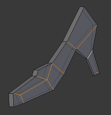 In the image to the right i have selected all unwanted edges. Just remove them and you end up with a half hollow shoe and that is exactly what we want.
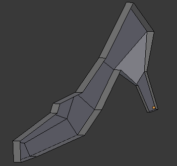 Now we only need to make the modifier visible again and we will end up with our first rough low polygon model of our new shoe. This model is as clean as possible (i hope i did not make any basic mistake) And it is well suitable for our ongoing activites.
When you enable visibility in the modifier, you will get another small triangle icon. When you also enable this one, then the mirrored vertices get displayed. And they even are selectable for edit.
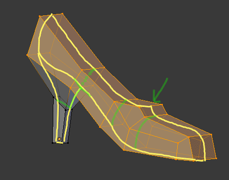
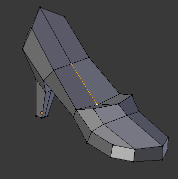 You can play and shift vertices around a bit. You will see that you can not break the mirror. I have spent a bit of fine adjusting the vertex locations and the end result of my basic model looks finally like in the image to the right.Our immediate next move will be to open the interior of the shoe to make it look more realistic. And we will want to make the shoe more smooth. We will do that in the next chapter.
