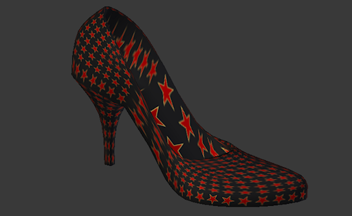
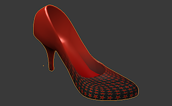
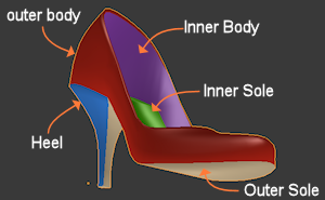
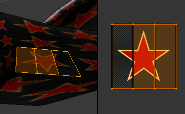
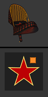
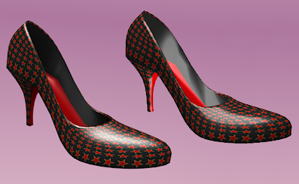
| One very common method to add color and structure (aka texturize) is by using 2D images (textures). The image content is then mapped to the surface of the 3D object. In more detail it works as follows:
Remember the basic building block of mesh objects are Faces. Since faces are flat, projecting flat images on them is easy.
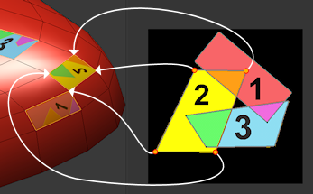
The image to the right illustrates the mapping from a flat image to the surface of a mesh object:
- On the left side of the image you see the tip of the shoe within the 3D view. I have selected one single face of the shoe.
- On the right side of the image you see a 2 dimensional (flat) image with a black background and one rectangle with the number “1” placed in its center..
The rectangle in the image is now projected on the selected face of the shoe. This projection is also called a mapping. The mapping is done on Vertex level: For each mapped Face actually its corner vertices are mapped from the image to the surface.
Note that the just described projection of one single face must be done for every face in the 3D view. At least if you want to cover the entire surface of your object.
Sometimes you will find that people make no distinction between “UV Texture” and “UV Map”. I think this is very missleading and i recommend that you take care here!
|

- It is common practice to name the axes of the flat image “U” and “V”. This helps for a better distinction from the 3D axes in the 3D view, which are usually named “X”, “Y” and “Z”.
- The flat image is typically named “Texture” and in our context it is often named UV Texture (because of the name “U” and “V” for the image axes).
- An area on the UV Texture which maps exactly to a Face in the 3D view is named UV Face. In the image above we see one UV Face mapped to one Face on the object.
- The mapping is actually the set of arrows which point from the UV texture to the 3D view. The entire set of arrows for one distinct mapping is also called UV Map.
Important: The UV Texture is an image. The UV Map tells how the image has to be placed (mapped) on the Object surface.
|
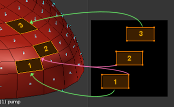
| In this example (see image on the right side) i have mapped 3 faces.
Some remarks:
- As mentioned before the mapping is done on Vertex level. Hence for each mapped Face actually its vertices are mapped.
- Consequently corresponding shapes of the 3D face and the 2D face must have the same number of vertices, but can have completely different form. For example none of the faces in the 3D space are perfect rectangles, but all of them are mapped to perfect rectangles in the UV Texture.
- Face 1 and Face 2 touch each other at one corner on the 3D Object. However the corner vertex can(!) be mapped to 2 separate locations on the 2D image. This is so because each 3D Face is mapped separately.
- 2 adjacent Faces on the 3D Object can be mapped to completely different areas in the UV Map. They do not need to touch. They even can partially or fully overlap.
- Take a closer look at Face 2 on the lower image. Do you see that this face gets mirrored on the Object surface ? Also see how overlapping areas of UV Faces on the UV Texture get mapped multiple times to the Model surface! There is nothing wrong with this UV Map!
|
The image below shows another (weird but fully legal) mapping:
Note: In practice you will not define the mapping by hand, but use a set of ready available “UV unwrapping tools” for this task.
|
A Nasty Pitfall
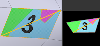
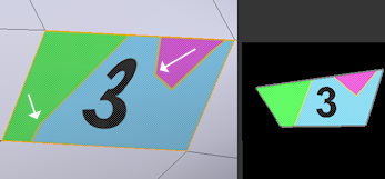
Take a closer look at the mapping of UV Face 3. The 2 white arrows point to areas of (maybe unexpected) distortion. Also the number “3” looks like it is too distorted. Why does that happen ?
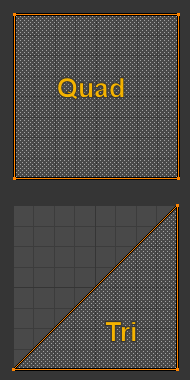
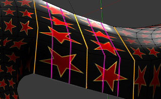
When it comes to rendering, Blender converts Quads to Triangles. Actually you can see what happens when you draw the internally used triangulation on the image.
|
|
